Advertisement
Quick Links
© June 2008 by Rotary Lift. All rights reserved. CO6962.4
SPO54
E And M
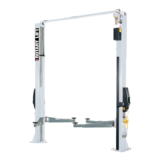
(600 & 700 Series)
Two Post Surface Mounted Lifts
I
N
N
S
S
T
T
A
A
L
L
L
L
A
A
TUV
TUV
T
T
Rheinland
Rheinland
I
O
O
N
N
I
N
N
S
S
T
T
R
R
U
U
C
C
T
T
I
O
O
N
N
S
S
IN20417
Rev. F 14/03/2016
I
I
I
I
Advertisement

Related Manuals for Rotary SPO54M


Summary of Contents for Rotary SPO54M
- Page 1 SPO54 E And M (600 & 700 Series) Two Post Surface Mounted Lifts Rheinland Rheinland © June 2008 by Rotary Lift. All rights reserved. CO6962.4 IN20417 Rev. F 14/03/2016...
- Page 2 Fig. 1 Fig. 2...
- Page 3 Figs. 1 And 2 Detail A 737mm B 1829mm Minimum to nearest obstruction or bay. 2134mm minimum nearest wall. C 1422mm D Power Unit E 3962mm Minimum to nearest obstruction. (14) 20mm Anchors G Apporach H 165mm Minimum to other equipment. 3962mm Minimum to nearest obstruction.
- Page 4 Attention: 6. Concrete and Anchoring: Concrete shall have a compression E Series Lifts DO NOT Have Latch Cable Guides strength of at least 20N/mm and a minimum thickness of 125mm or Locking Latch Cables. in order to achieve a minimum anchor embedment of 95mm. When using the standard supplied 20mm x 170mm lg.
- Page 5 7. IMPORTANT: Using the horse shoe shims provided, shim each column base until each column is plumb, Fig. 7. If one column has to be elevated to match the plane of the other column, full size base shim plates should be used (Reference Shim Kit). Recheck columns for plumb.
- Page 6 8. Overhead Assembly: Adjust overhead to 2896mm between Then secure HHCS and Switch Bar to overhead as shown, centerline of sheave pins, Fig. 8. Install (2) 3/8"-16NC x 3/4" using (2) 19mm spacer and 1/4”-20NC Lock Nut. Tighten Hex Flanged HHCS & Flanged Lock Nuts, do not tighten. Install bolt leaving 1.6mm gap between the spacer and the overhead overhead stiffener angle inside center of overhead using (4) 3/8"- assembly.
- Page 7 CAUTION CAUTION Installation of power unit for E series Continue to section 13. lifts go to section 11. 10. Power Unit for M Series Lifts: A. Install (1) star washer onto one of the (4) 5/16"-18NC x 1-1/2” Lg. HHCS. This is very important for grounding. Put the (4) 5/16"-18NC x 1-1/2"...
- Page 8 11. Power Unit E Series Lifts: Put (2) 5/16"-18NC x 1-1/2" HHCS through top holes in power unit bracket using Vibration Pad to hold in place, Fig. 12. Install 5/16"-18NC Flanged Nuts until bolt end is flush with end of nut. Install power unit onto column extension, Fig.
- Page 9 13. Hoses: Clean adapters and hose. Inspect all threads for 2. Install item. (3) with hose clamps item (5) starting at opposite damage and hose ends to be sure they are crimped. Install hose cylinder and working toward the power unit. All excess hose using Flared Fittings Tightening Procedure, Section 12.
- Page 10 15. Equalizing Cables: H) Repeat procedure for the second cable. Adjust the tension A) Remove sheave cover, Fig. 15. of both cables during the final adjustments in section. See Section 36 for E series lifts and Section 39 for M series lifts. CAUTION For E Series Lifts Continue To Section 20.
- Page 11 16. Locking Latch Cable: D) Attach latch cable conduit guide brackets to overhead as A) Install latch cable sheave, sheave covers, and retaining rings shown, Fig. 21a & Fig. 21b. Always use the holes on the in upper slot of power unit column as shown, Fig. 19. approach side of the lift.
- Page 12 Route cable under the bottom side of the latch cable sheave, K) Insert cable in cable clamp along one side, loop around Fig. 22. shoulder screw and back down, inserting cable along other J) At this point you MUST install the latch handle, jam nut, and side of cable clamp, Fig.
- Page 13 NOTES: 1.) Units not suitable for use in unusual conditions. Contact Rotary for moisture and dust environment duty units. 2.) Motor rotation is counter clockwise from top of motor. MOTOR OPERATING DATA - SINGLE PHASE (*F Model) LINE VOLTAGE...
-
Page 14: Line Voltage
19. Check Operation: Operate lift and assure that push button raises lift when pushed and stops lift when released. Check disconnect switch for cutting power to push-button. Also check that overhead switch stops lift from raising when actuated and that lift regains power when deactivated. Attention: Continue to Section 29. - Page 15 Installing Electrical And Inbay Controller Components 21. Installing Master Control Panel & Tool Holder: Remove access panel from the master control panel (master For E Series Lifts. control panel has 5 cables attached to it), Fig. 27. Install (2) 5/16"-18NC x 3/8" PHMS screws in holes on each side 20.
- Page 16 21b. Install Master Cable Motor Cable to Master panel connections. Fig. 27 Fig. 27 Detail Fig. 27 Detail 5/16"-18NCx3/8" PHMS, Leave these two screws Pull connector through panel exposed out of the column approximately 3mm. Overhead Switch Cable IMPORTANT Master Cable Master control panel always mounts on the power unit side.
- Page 17 22. Routing Motor and Master Cables: From the master control panel route cables up through column along the hose routing, Fig. 28. Fig. 28 Fig. 28 Detail Master control wire routing follows hydraulic hose routing Fig. 29 Fig. 29 Detail A) Locate the overhead switch cable at the master cable 5/16"-18NCx3/8"...
- Page 18 Fig. 30 Detail Fig. 30 A 5 wire power connection from slave control panel. B Power harness or extension for power harness follows hydraulic hose back to slave control panel. C 3 wire from master control panel goes through stra- in relief into junction box on powerunit motor.
- Page 19 24. Slave Cable & Disconnect Harness Routing: C) Run slave cable up through the column along hose routing. A) Remove cover panel from slave control side, Fig. 31 D) Secure cable to structure with wire ties and away from disconnecting the pushbutton cable from slave harness. equalization cables.
- Page 20 Fig. 31a Three Phase Detail A Facility power connects into the top of the discon- nect. B Power harness to Master Control panel connects into the bottom of the disconnect. C Connection plugs into solenoid. D Connection plugs into back of slave panel for button controls.
- Page 21 NOTES: 1. Unit not suitable for use in unusual conditions. Contact Rotary Lift for moisture and dust environment duty unit. 2. Motor rotation is counter clockwise from top of motor. Fig. 32 Single Phase Motor Wiring 220V/50Hz A Connection from Master Control panel.
- Page 22 Power supply Disconnect switch Black Black Power unit area Black Black 1-phase Black Black 220V Green/Yellow Green/Yellow Black Black Black Black 3-phase Blue Motor* 380, 400V Slave enclosure Overhead Lowering switch valve Green/Yellow Motor relay Disconnect switch European 2 1 2 3 4 Black Black Black...
- Page 23 Installing Gaskets To Master And Slave Enclosures: IMPORTANT These gaskets must be installed to maintain CE certification A) To install gasket on master side control, locate the (4) 5/16"-18NCx3/8" BHCS that hold down the black enclosure and loosen them by 3 or 4 turns, Fig. 33. Also loosen the (2) upper and (1) lower 5/16"-18NCx3/8"...
- Page 24 B) To install gasket on the slave side, loosen the (2) upper and (1) lower 5/16"-18NCx3/8" PHMS that hold the control unit to the column. Fit the gasket behind the black enclosure, make sure to plug in all connections, and reinstall with (4) 5/16"-18NCx3/8"...
- Page 25 27. Power Up For E Series Lifts: Turn disconnect to ON position from the master control panel, Fig. 34. Note: Lift can only be powered up from the Master Control Side. The Slave Control side only runs the lift. Fig. 34 A Raise Lift B Lower Lift C Lower To Locks...
- Page 26 28. Web covering and wire chase placement, Fig. 35: Start by wire tying all the wires and hoses neatly and out of the way of the cables. Place edge and rib gaskets around wire chases. Take one of the wire chases and attach it to one of the control panels with two #8-32NC x 5/8"...
- Page 27 29. Arms & Restraints: Before installing arms, raise carriages WARNING to a convenient height. Grease swivel arm pins and holes with Lithium grease. Slide arm into yoke, Fig. 36a. Install 1-3/4" diameter arm pin(s), Fig. 36a. After installing arms and pins, install arm Restraint Gears as follows: Install Restraint Gear onto arm clevis, as shown, Fig.
- Page 28 Fig. 36c Fig. 38 NOTE: To check operation of arm restraints, raise carriage 1” min. from full down position. Pull up on pin-ring and adjust arms to desired position. To engage restraint, let pin-ring down allowing gear teeth to mesh together. It may be necessary to rotate arm slightly to engage gear teeth.
- Page 29 Fig. 39 Detail A (6) 5/16" Flat Washers B (2) 5/16" Spring Lock Washers C (2) 5/16"-18NC HHCS (per arm) D Arm Guard (For SPO40M the different arm guard goes on the right front arm, see Fig. 2b) Fig. 39 if t O R a is h e s...
- Page 30 Fig. 42 Detail A E Series Power Units B M Series Power Units C Access for pressure reading Fig. 42 39. Equalizer Test For M Series lifts: Raise lift to check equalizer 34. Oil Bleeding for E Series lifts: cable tension. Below carriage, grasp adjacent cables between Press on touch pad and raise lift about 609mm.
- Page 31 NOTES...
- Page 32 Thank You Trained Operators and Regular Maintenance Ensures Satisfactory Performance of Your Rotary Lift. Contact Your Nearest Authorized Rotary Parts Distributor for Genuine Rotary Replacement Parts. See Literature Package for Parts Breakdown. е European World Wide Contact Information Headquarter World Headquarters/USA: 1.812.273.1622...
Need help?
Do you have a question about the SPO54M and is the answer not in the manual?
Questions and answers