Advertisement
Available languages
Available languages
Quick Links
IMPORTANT SAFEGUARDS
When using electrical equipment, basic safety precautions should always be followed
including the following:
READ AND FOLLOW ALL SAFETY
INSTRUCTIONS
1.
DANGER- Risk of shock- Disconnect power before installation.
DANGER – Risque de choc – Couper l'alimentation avant l'installation.
2.
This luminaire must be installed in accordance with the NEC or your local
electrical code. If you are not familiar with these codes and requirements, consult
a qualified electrician.
Ce produit doit être installé conformément à NEC ou votre code électrique local.
Si vous n'êtes pas familier avec ces codes et ces exigences, veuillez contacter un
électricien qualifié.
SAVE THESE INSTRUCTIONS FOR
FUTURE REFERENCE
TO INSTALL:
1
3
1 of 3
2
4
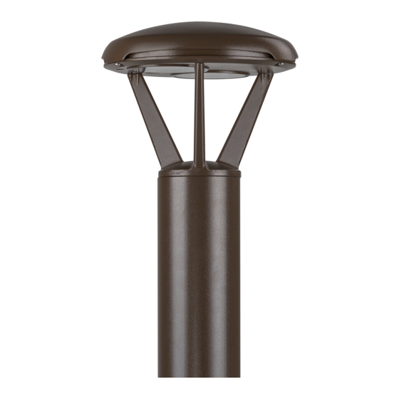
THE EDGE
INSTALLATION INSTRUCTIONS
INSTRUCTIONS D'INSTALLATION
REMOVING EXISTING BOLLARD
STEP 1:
To remove existing Bollard Pole from anchor
bolts, remove four 1/4-20 flat head screws at
base of pole and lift off pole and lens assembly
vertically. See Figure 1.
STEP 2:
Disconnect electrical supply connections.
STEP 3:
Remove nuts and jam nuts from anchor bolts
and set aside. Remove the inner frame assembly
and 8" base plate from anchor bolts.
INSTALL PATHWAY
STEP 1:
Remove 4" base plate from bottom of new
Pathway pole by removing three 1/4-20 flat head
screws at base of pole. See Figure 2.
STEP 2:
Connect 4" Pathway Base to steel transition
plate supplied in Retrofit Kit by inserting three
3/8 x 2.00 flat head screws up through the steel
plate and up through the bottom of the base.
Figure 3.
Secure with nuts. See
STEP 3:
Position the transition plate over existing anchor
bolts and secure with nuts set aside from Step 3.
STEP 4:
Attach L bracket to hole in transition plate using
#8 x 0.25 screw.
STEP 5:
Loosen 3/8-16 pan head screw located at the
arm base of optic assembly using a T-45 torx
Figure 4.
socket and ratchet. See
STEP 6:
Lift optic assembly from pole.
®
LED Pathway
Includes: XBP
CI347X02R1_B
Advertisement

Related Manuals for CREE LIGHTING EDGE Series


Summary of Contents for CREE LIGHTING EDGE Series
-
Page 1: Important Safeguards
THE EDGE ® LED Pathway Includes: XBP IMPORTANT SAFEGUARDS INSTALLATION INSTRUCTIONS INSTRUCTIONS D’INSTALLATION When using electrical equipment, basic safety precautions should always be followed including the following: READ AND FOLLOW ALL SAFETY INSTRUCTIONS DANGER- Risk of shock- Disconnect power before installation. DANGER –... - Page 2 STEP 7: DIRECT CONCRETE MOUNT STEP 6: Pull wire up through pole and then reattach Lift optic assembly from pole. STEP 1: pole to base with the three ¼-20 flat head STEP 7: screws removed in step 1. Follow Step 1 and Step 2 from “INSTALL Pull wire up through pole and then reattach PATHWAY”...
- Page 3 3" (76 mm) dia. hole (3) required available conduit entry © 2019 Cree Lighting, A company of IDEAL INDUSTRIES. All rights reserved. For informational purposes only. Content is subject to change. See www.creelighting.com/warranty for warranty and specifications. Cree and the Cree logo ®...
- Page 4 THE EDGE ® LED Pathway CONSEJOS IMPORTANTES INSTRUCCIONES DE INSTALACIÓN - ESPAÑOL DE SEGURIDAD Al usar equipos eléctricos, siempre se deben seguir precauciones de seguridad básicas, incluidas las siguientes: LEA Y SIGA TODAS LAS INSTRUCCIONES DE SEGURIDAD DANGER- Para evitar una posible descarga eléctrica, apague el suministro de energía antes de la instalación o de realizar mantenimiento.
- Page 5 PASO 5: plana de 3/8-16 en 240 lb pulg. Consulte la ubicado en la base del brazo de ensamblado Figura 5. óptico con una llave de cubo Torx T-45. Afloje el tornillo de cabeza plana de 3/8-16 Consulte la Figura 4. ubicado en la base del brazo de ensamblado MONTAJE DIRECTAMENTE EN EL óptico con una llave de cubo Torx T-45.
- Page 6 76 mm (3 pulg.) de diámetro © 2019 Cree Lighting, una compañía de IDEAL INDUSTRIES. Todos los derechos reservados. Sólo para fines informativos. El contenido está sujeta a cambios. Consulte www.creelighting.com/warranty para la garantía y las especificaciones. Cree® y el logotipo de Cree son marca registrada de Cree, Inc.
Need help?
Do you have a question about the EDGE Series and is the answer not in the manual?
Questions and answers