Table of Contents
Advertisement
Quick Links
Advertisement
Table of Contents
Troubleshooting

Subscribe to Our Youtube Channel
Related Manuals for Tempsens CALsys 250


Summary of Contents for Tempsens CALsys 250
- Page 1 CALsys 250 Liquid Temperature Calibrator CALsys 250 USER MANUAL P a g e...
-
Page 2: Table Of Contents
CALsys 250 Contents Safety Information ........................4 3. Introduction…………………………………………………………………………………. 8 3.1 Basic working of CALsys 250...………………………………………………………….. 9 3.2 Dimension……………………………………………………………………………… 10 3.3 Wiring Diagram……………………………………………………………………… 4. Technical Specification: ...................... 122 5. Installation….…………………………………….……………………………………… 13 5.1 Environmental Condition……………………………………………………………….. 13 6. Unpacking & Initial Inspection…………………………………………………………... - Page 3 CALsys 250 Preface Thank you for purchasing High Quality and Efficient CALsys 250. Please familiarize yourself with the information contained in the safety precautions sections before using this product. This user manual contains information about the product and its proper use and should be kept in a place where it will be easy to access.
-
Page 4: Safety Information
CALsys 250 Safety Information This chapter contains important information for the safety. The not observance of these instructions may result in serious personal injury or can cause serious damage to the unit and to the components system included. Use the instrument only as specified in this manual. - Page 5 CALsys 250 Before connecting to the electricity supply, please familiarize yourself with the parts of the calibrator with the help of operating manual. Always replace the fuse with one of the same rating, voltage and type. Use only the mains power cord and connect or approved for the voltage and plug Configuration in your country and rated for the Product.
- Page 6 CALsys 250 There are no user serviceable parts inside. Contact Tempsens agent for repair. Ensure materials, especially flammable materials are kept away from hot parts of the apparatus, to prevent fire risk. Do not use the Product around explosive gas, vapor, or in damp or wet environments.
- Page 7 CALsys 250 CAUTIONS To avoid possible damage to the instrument, follow these guidelines. DO NOT connect this unit to a non-grounded, non-polarized outlet. Before working inside the equipment, turn the power off and disconnect the power cord. Always replace the fuse with one of the same rating, voltage, and type.
-
Page 8: Introduction
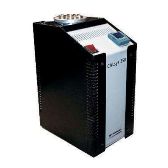
CALsys 250 3. Introduction: The ‘CALsys 250’ has been designed to provide stable and accurate temperature to enable professionals calibrate Temperature Sensing Devices by comparison method. The ‘CALsys 250’ model has been designed to be rugged and easily maintained. This model provides an isothermal enclosure (Aluminium block) in which the thermocouple/RTD can be calibrated against the temperature of the calibrator. -
Page 9: Basic Working Of Calsys 250
CALsys 250 3.1 Basic Working of CALsys 250: The calibrator controller uses a PT-100 sensor as a controlling sensor and controls the chamber temperature with Cartridge Heater. obtain maintain a required temperature the controller varies the power to the heater via solid-state relay. -
Page 10: Dimension
CALsys 250 3.2 Dimension: 10 | P a g e... -
Page 11: Wiring Diagram
CALsys 250 3.3 Wiring Diagram: 11 | P a g e... - Page 12 CALsys 250 4. Technical Specification: 230 V AC±10 Voltage Power 1.5 KW Supply Frequency 50/60 Hz 50 to 250°C Temperature range Resolution 0.1 °C ± 0.015°C at 50 °C Stability ± 0.025°C at 150 °C ± 0.050°C at 250 °C Uniformity ±...
-
Page 13: Technical Specification
CALsys 250 5. Installation: Place the Calibration Bath on a flat surface with at least 10 inches of free space around the instrument. Overhead clearance is required. DO NOT Place this unit under a cabinet or structure. Plug the power cord into a grounded mains outlet located on the controlling unit rear panel. -
Page 14: Unpacking& Initial Inspection
Unpack the Furnace carefully and inspect. If you find any damage or any item is missing notify us or our agent. After unpacking you will find the following accessories CALsys 250…………………..1 No Power cord ……………………..1 No RS-232 Cable and Software CD... -
Page 15: Installation
CALsys 250 6.1 Instructions: 1. Please open the carrying case carefully and takeout the operating manual from the box and read carefully. 2. Take out the Bath carefully and keep it at suitable place. 3. Connect the power plug to the rear power entry and connect the power plug to the mains. -
Page 16: Operating Instruction
CALsys 250 7. Operating Instruction: 7.1 Power Plug the calibration bath power cord into mains outlet of the proper voltage, frequency and current capability. Typically this will be (230 VAC±10, 50/60 Hz). Turn the controller using the “Mains” switch located on the controlling section and set the temperature value in the controller. -
Page 17: Operating Instruction
Directly, First set the controller to 0 Deg C and then wait until the unit is not cooled below 100 Deg C. 7.3 Operating Instruction: 1. Connect the ‘CALsys 250’ to a suitable power supply. 2. Fill the oil in the bath, up to the marked line, Connect the power Supply to the heater and stirrer. - Page 18 11. When the calibration is completed, reset the controller to 0°C & wait until the unit has cooled to below 100°C, before moving the ‘CALsys 250’ to new location the ‘CALsys 250’ must be cooled to below 100°C.
-
Page 19: Operation Of Controller
CALsys 250 8. Operation Of controller: FRONT PANEL LAYOUT 8.1 The Temperature Controller The controller has a dual display, the upper display indicates the measured temperature, and the lower display indicates the desired temperature or set point. 8.2 Altering the Set point To change the set point of the controller simply use the UP and DOWN keys to raise and lower the set point to the required value. -
Page 20: Monitoring The Controller Status
CALsys 250 8.3 Monitoring the Controller Status A row of beacons indicate the controllers status as follows, OP1 Heat Output OP2 Cool Output (only for models which operate below 0°C) REM This beacon indicates activity on the PC interface 8.4 Units Momentary pressing of the Scroll key will show the controller units °C or °F. -
Page 21: Auto Tune
CALsys 250 r.tc R thermocouple (Pt/Pt13%Rh) b.tc B thermocouple (Pt30%Rh/Pt6%Rh) n.tc N thermocouple t.tc T thermocouple S.tc S thermocouple (Pt/Pt10%Rh) PL.2 PL 2 thermocouple PT-100 platinum resistance thermometer. T012 E thermocouple Again the value can be modified with the UP and DOWN keys. -
Page 22: Offset
CALsys 250 8.6.3 How to know Auto tune has done: Whenever ‘AUTO TUNE’ is ‘ON’ there will always be a rolling message ‘AUTO TUNE’ on display of controller. When the display is not showing this continues message it means Auto tune is complete. - Page 23 CALsys 250 9. Digital Communications: RS-232 is a standard communication protocol for linking computer and its peripheral devices to allow serial data exchange. RS-232 communications uses the Modbus protocol. Rs-232 communications is not available if Remote Set point is fitted. Cable screen should be grounded at one point only to prevent earth loops.
- Page 24 CALsys 250 9.1 Digital Communications Wiring To use EIA232 the PC will be equipped with an EIA232 port, usually referred to as COM 1.To construct a cable for EIA232 operation use a three core screened cable. The terminals used for EIA232 digital communications are listed in the table below. Some PC's use a 25 way connector although the 9 way is more common.
- Page 25 CALsys 250 9.2 Digital Communications Parameters The following table shows the parameters available. 25 | P a g e...
- Page 26 CALsys 250 9.3 Broadcast Communications The 3200 broadcast master can be connected to up to 31slaves if no segment repeaters are used. If repeaters are used to provide additional segments, 32 slaves are permitted in each new segment. The master is configured by setting the ‘RETRN’ parameter to W.SP, PV, OP or Err.
- Page 27 CALsys 250 10. Software Installation: The provided Tempsens software offers possibilities to connect furnace temperature bath and change set point, maximum time span, view real time graph and evaluate measuring data. 10.1 Installation Install the calibration software using the installation guide file on CD ROM. After installation of the software;...
- Page 28 Tempsens furnace. Communication can be done by clicking on connect and select correct COM port address (fig. 1) where furnace is connected. Also user has to select type of controller version3216 (fig.
- Page 29 CALsys 250 PVI Value: - Read the current PV value (present value of furnace temperature). File will be stored in .xls format to save previous record open the file by clicking on menu file open. 29 | P a g e...
-
Page 30: Initial Testing
This unit is fully tested before dispatch to you but please check its operation as outlined below. Step 1: After connecting the CALsys 250 to the electricity supply, the temperature controller display will show the temperature of the chamber and the last set-point value. -
Page 31: Maintenance & Trouble Shooting
CALsys 250 12. Maintenance & Trouble shooting:- 12.1 Routine service: Turn the electricity supply off before attempting any cleaning operation. The only moving part is the fan. That has sealed-for-life bearings. Depending on the environment in which it is used, periodic cleaning is recommended. Cleaning may be accomplished by the use of a small dry paint brush. - Page 32 CALsys 250 6. Tighten the fixing screws. 7. Refit the wires has been noted in step 4. 8. Replace the cover. 9. Reconnect the furnace to the electrical supply. NOTE: The calibration instrument has been designed with the utmost care. Ease of operation and simplicity of maintenance have been a central theme in the product development.
- Page 33 CALsys 250 It is important to keep the well of the calibrator clean and clear of any foreign matter. DO NOT use chemicals to clean the well. The bath should be handled with care. Avoid knocking or dropping the instrument.
-
Page 34: Troubleshooting
CALsys 250 13. Troubleshooting: 1. Unit fails to operate Check fuse, if fuse blows repeatedly consult us. 2. Unit unstable Control parameters have been interfered with - consult us. 3. If the temperature of the calibrator is not rising, ensure the followings: The power cord should be not loose at power entry. - Page 35 INTERFERENCE WITH OR FAILURE TO PROPERLY MAINTAIN THIS INSTRUMENT MAY INVALIDATE THIS GUARANTEE Limit of Liability TEMPSENS not liable for any damages that arise from the use of any examples or processes mentioned in these Specifications are subject to change without notice. CAUTIONARY NOTE...
-
Page 36: Recommendation
Recommendation The life of your ‘CALsys 650’ instrument will be prolonged if regular maintenance and cleaning to remove general dust and debris is carried out. Tempsens Instruments (I) PVT. LTD. Unit- II A-190, Road No. 5, M.I.A. Udaipur 313003 India... - Page 37 CALsys 250 NOTE 37 | P a g e...
- Page 38 CALsys 250 38 | P a g e...
Need help?
Do you have a question about the CALsys 250 and is the answer not in the manual?
Questions and answers