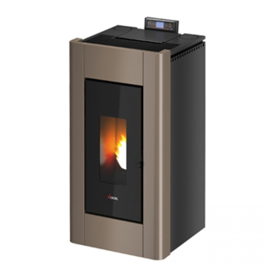
Cadel IDRO PRINCE 3 12 Installation, Use & Maintenance Manual

Cadel IDRO PRINCE 3 12 Installation, Use & Maintenance Manual

Pellet thermostove
Table of Contents

Advertisement

PELLET THERMOSTOVE
en
,
installation
use and maintenance manual
IDRO PRINCE
12 - IDRO PRINCE
16 - AQUOS
16 - IDRON 16 AIRTIGHT - MIRA 16 -
3
3
3
TESIS 16 AIRTIGHT - IDRO PRINCE
23 - AQUOS
23 - IDRON 22 AIRTIGHT - HIDROFIRE 22.8 - MIRA
3
3
22 - TESIS 22 AIRTIGHT - IDRO PRINCE
23 H
O - AQUOS
23 H
O - IDRO PRINCE 30 -
3
3
2
2
IDRO PRINCE 30 H
O
2
©2019 CADEL srl | All rights reserved – tutti i diritti riservati

Advertisement

Table of Contents
loading

Summary of Contents for Cadel IDRO PRINCE 3 12

  • Page 1 23 - IDRON 22 AIRTIGHT - HIDROFIRE 22.8 - MIRA 22 - TESIS 22 AIRTIGHT - IDRO PRINCE 23 H O - AQUOS 23 H O - IDRO PRINCE 30 - IDRO PRINCE 30 H ©2019 CADEL srl | All rights reserved – tutti i diritti riservati...
  • Page 2: Table Of Contents

    7.1 PLUMBING SYSTEM CONNECTION......32 SUMMARY 7.2 CONNECTION DIAGRAM (IDRO PRINCE 12) ..32 7.3 CONNECTION DIAGRAM IDRO PRINCE 16-23 , AQUOS 1 INTRODUCTION ..........2 16-23 , IDRON 16-22 AIRTIGHT, HIDROFIRE 22.8 - MIRA 16- 1.1 REVISIONS TO THE PUBLICATION ......2 22 - TESIS 16-23 AIRTIGHT ..........33 1.2 CARE OF THE MANUAL AND HOW TO CONSULT IT ...2 7.4 CONNECTION DIAGRAM IDRO PRINCE 30 .....34 1.3 SYMBOLS USED IN THE MANUAL ......2...
  • Page 3 12.3 SMOKE TEMPERATURE PROBE ......54 12.4 CONTACT THERMOSTAT IN THE FUEL HOPPER..54 12.5 CONTACT THERMOSTAT IN THE BOILER ....54 12.6 WATER TEMPERATURE PROBE.......54 12.7 ELECTRICAL SAFETY ..........54 12.8 SMOKE FAN ............54 12.9 GEAR MOTOR ............54 12.10 TEMPORARY POWER CUT ........54 12.11 FAILED START-UP ..........55 12.12 ANTIFREEZE FUNCTION .........55 12.13 PUMP ANTI-SEIZURE FUNCTION ......55...
  • Page 4: Introduction

    No part of this manual can be translated into another language and/or altered and/or reproduced, even partially, in another form, by mechanical or electronic means, photocopied, recorded or similar, without prior written approval from CADEL srl. The company reserves the right to make changes to the product at any time without prior notice. The proprietary company reser- ves its rights according to the law.
  • Page 5: Warnings And Warranty Terms

    WARNINGS AND WARRANTY TERMS SAFETY WARNINGS Installation, electrical connection, operational testing, and maintenance must be done exclusively by authorised qualified personnel. Install the product in accordance with all local and national laws, as well as with the standards in force in the town, region, or nation.
  • Page 6: Information

    IMMEDIATELY CONTACT THE INSTALLATION/CUSTOMER SERVICE TECHNICIAN. INFORMATION • If you have any issues, contact the retailer or a qualified technician authorised by Cadel; if repairs are required, ask them to use original spare parts. • Only use the type of fuel recommended by Cadel (in Italy, 6mm-diameter pellets and in other European countries, 6-8mm- diameter pellets), which must be loaded solely via an automatic feed system.
  • Page 7: Warnings On Proper Product Disposal

    instructions provided. • Further damage caused by the user tampering with the appliance in an attempt to resolve the initial malfunction. • Increased damage caused by the user continuing to the use the appliance after the defect appeared. • If there is a boiler, any corrosion, build-ups, or breakages caused by stray current, condensation, harsh or acidic water, inappro- priate descaling treatments, lack of water, sludge or limescale deposits.
  • Page 8: Installation

    INSTALLATION STANDARDS The product in question is a wood pellet fuelled stove. The following are some European reference standards for product installation: EN 12828 Design for heating systems. IEC 64-8 Electrical systems at a rated voltage not exceeding 1000V in alternating current and 1500V in direct current. EN 1443 Chimneys.
  • Page 9: Foreword

    The poorer the quality of the fuel, the more often the internal parts of the brazier and combustion chamber must be cleaned. DINplus, Ö-Norm M7135 and Pellet gold are examples of the major quality certifications of pellets in the European market and guarantee that the following are complied with: •...
  • Page 10: Foreword

    Fig. 2 - Safety distance MODEL NON-FLAMMABLE WALLS FLAMMABLE WALLS IDRO PRINCE A = 5 cm / B = 5 cm A = 20 cm / B = 20 cm IDRO PRINCE 16-23-23 H2O A = 5 cm / B = 5 cm A = 20 cm / B = 20 cm IDRO PRINCE 30-30 H2O A = 5 cm / B = 5 cm...
  • Page 11: Technical Features

    Fig. 3 - Flue TECHNICAL FEATURES Have a qualified technician check flue efficiency. The flue must be airtight, vertical without constrictions, made with materials that are resistant to smoke and condensate, thermal- ly insulated, and suited to resist normal mechanical stresses over time (we recommend circular section insulated twin wall chim- neys in A/316 or refractory material).
  • Page 12 15° Fig. 5 - 15° roof LEGEND Fig. 5 min. 1.00 metre distance > 1.85 metres distance < 1.85 metres 0.50 metres beyond the top 0.50 metres backflow area 30° Fig. 6 - 30° roof LEGEND Fig. 6 min. 1.30 metres distance >...
  • Page 13 60° Fig. 7 - 60° roof LEGEND Fig. 7 min. 2.60 metres distance > 1.20 metres distance < 1.20 metres 0.50 metres beyond the top 2.10 metres backflow area 45° Fig. 8 - 45° roof LEGEND Fig. 8 min. 2.00 metres distance >...
  • Page 14: Sizing

    SIZING The vacuum (draft) of a flue also depends on its height. Check vacuum with the values shown in the technical features. Minimum flue height is 3.5 metres. The flue internal cross-section can be circular (best case), square, or rectangular (the ratio between the inner sides must be ≤1.5) with the sides coupled with a 20mm minimum radius.
  • Page 15: Chimney Components

    3.11 CHIMNEY COMPONENTS Fig. 10 - Chimney components LEGEND Fig. 10 Chimney cap Backflow duct Smoke duct Thermal insulation External wall Chimney fitting Smoke channel Heat generator Inspection door 3.12 OUTSIDE AIR VENT It is mandatory to create an adequate outside air vent that supplies the combustion air necessary for the product to work properly. The flow of air between the outside and the installation room can be direct, via an opening on an external wall of the room (see “Solution 1”...
  • Page 16 Fig. 11 - Solution 1 = directly from the outside Fig. 12 - Solution 2 = indirectly from an adjacent room LEGEND Fig. 11 - Fig. 12 Air vent Room to ventilate Increased space beneath the door The air needed for combustion can be directly connected to the outside air vent with a pipe of at least Ø50 mm, at most 3 linear metres long;...
  • Page 17: Connection To The Flue

    3.13 CONNECTION TO THE FLUE The appliance must be connected to the flue by a smoke duct compliant with EN 1856-2. The connection must be at most 4m long horizontally, with a minimum 3% slope and at most three 90° elbows (that can be inspected - the appliance outlet T-fitting does not count).
  • Page 18 Fig. 14 - Example of proper installation LEGEND Fig. 14 Insulation Potential reduction from 100 to 80 mm Inspection cap Inspection door Air vent T-fitting with inspection cap Minimum 40 mm Maximum 4 m Minimum 3° Minimum 400 mm Hole diameter See TECHNICAL FEATURES a pag.
  • Page 19: Drawings And Technical Features

    DRAWINGS AND TECHNICAL FEATURES IDRO PRINCE 12 DIMENSIONS Fig. 15 - Idro Prince LEGEND Fig. 15 52 cm 52,7 cm 100 cm 22,3 cm 15,5 cm 33,5 cm 20,8 cm Exhaust fumes d.8 cm Hole combustion air inlet d.5 cm IDRO PRINCE 12-16-23-23 H O - IDRO PRINCE 30-30 H...
  • Page 20: Idro Prince 16-23-23 H O Dimensions

    IDRO PRINCE 16-23-23 H O DIMENSIONS Fig. 16 - Idro Prince 16-23-23 H LEGEND Fig. 16 52 cm 52,7 cm 109,8 cm 22,3 cm 15,5 cm 33,5 cm 20,8 cm Exhaust fumes d.8 cm Hole combustion air inlet d.5 cm IDRO PRINCE 12-16-23-23 H O - IDRO PRINCE 30-30 H...
  • Page 21: Dimensioni Stufa Idro Prince 30 - 30 H O

    DIMENSIONI STUFA IDRO PRINCE 30 - 30 H Fig. 17 - Idro Prince 30-30 H LEGEND Fig. 17 69 cm 68,5 cm 135,5 cm 42,8 cm 15,1 cm 48,6 cm 25,2 cm Exhaust fumes d.10 cm Hole combustion air inlet d.8 cm IDRO PRINCE 12-16-23-23 H O - IDRO PRINCE 30-30 H...
  • Page 22: Aquos

    AQUOS 16-23-23 H O DIMENSIONS Fig. 18 - Aquos 16-23-23 H LEGEND XREF-2:10645] 54,6 cm 57,5 cm 109,5 cm 23 cm 17,3 cm 34 cm 22,5 cm Exhaust fumes d.8 cm Hole combustion air inlet d.5 cm IDRO PRINCE 12-16-23-23 H O - IDRO PRINCE 30-30 H O - AQUOS 16-23-23 H...
  • Page 23: Tesis 16-23 Airtight Dimensions

    IDRON 16-22 AIRTIGHT - HIDROFIRE 22.8 - MIRA 16-22 - TESIS 16-23 AIRTIGHT DIMENSIONS Fig. 19 - Idron 16-22 Airtight / Hidrofire 22.8 / Mira 16-22 /Tesis16-23 LEGEND Fig. 19 52,5 cm 51,5 cm 109 cm 23 cm 14,5 cm 34 cm 20 cm Exhaust fumes d.8 cm...
  • Page 24: Technical Features

    TECHNICAL FEATURES DESCRIPTION IDRO PRINCE IDRO PRINCE AQUOS 11,8 kW (10.148 kcal/h) 16,2 kW (13.932 kcal/h) 16,2 kW (13.932 kcal/h) Effective rated power 10,2 kW (8.772 kcal/h) 12,9 kW (11.094 kcal/h) 12,9 kW (11.094 kcal/h) Effective rated power (H Minimum effective power 3,2 kW (2.752 kcal/h) 4,7 kW (4.042 kcal/h) 4,7 kW (4.042 kcal/h)
  • Page 25 DESCRIPTION IDRON 16 AIRTIGHT MIRA 16 TESIS 16 AIRTIGHT Effective rated power 16,2 kW (13.932 kcal/h) 16,2 kW (13.932 kcal/h) 16,2 kW (13.932 kcal/h) Effective rated power (H 12,9 kW (11.094 kcal/h) 12,9 kW (11.094 kcal/h) 12,9 kW (11.094 kcal/h) Minimum effective power 4,7 kW (4.042 kcal/h) 4,7 kW (4.042 kcal/h)
  • Page 26 DESCRIPTION IDRO PRINCE 23-23 H2O AQUOS 23-23 H2O IDRON 22 AIRTIGHT Effective rated power 22,8 kW (19.608 kcal/h) 22,8 kW (19.608 kcal/h) 22,8 kW (19.608 kcal/h) Effective rated power (H 18,7 kW (16.082 kcal/h) 18,7 kW (16.082 kcal/h) 18,7 kW (16.082 kcal/h) Minimum effective power 4,7 kW (4.042 kcal/h) 4,7 kW (4.042 kcal/h)
  • Page 27 DESCRIZIONE IDROFIRE 22.8 MIRA 22 TESIS 23 AIRTIGHT Effective rated power 22,8 kW (19.608 kcal/h) 22,8 kW (19.608 kcal/h) 22,8 kW (19.608 kcal/h) Effective rated power (H 18,7 kW (16.082 kcal/h) 18,7 kW (16.082 kcal/h) 18,7 kW (16.082 kcal/h) Minimum effective power 4,7 kW (4.042 kcal/h) 4,7 kW (4.042 kcal/h) 4,7 kW (4.042 kcal/h)
  • Page 28 DESCRIZIONE IDROPRINCE 30 IDROPRINCE 30 H2O Effective rated power 28,62 kW (19.608 kcal/h) 28,62 kW (19.608 kcal/h) Effective rated power (H 26,99 kW (16.082 kcal/h) 26,99 kW (16.082 kcal/h) Minimum effective power 7,76 kW (4.042 kcal/h) 7,76 kW (4.042 kcal/h) Minimum effective power (H 6,28 kW (2.666 kcal/h) 6,28 kW (2.666 kcal/h)
  • Page 29: Installation And Assembly

    INSTALLATION AND ASSEMBLY PREPARATION AND UNPACKING The product is packaged in a recyclable cardboard box according to RESY standards, on a wood pallet. All the packaging materials can be reused for similar purposes or, in the event, disposed of as waste assimilable to urban solid waste, following the standards in force. After having removed the packaging, make sure the product is intact.
  • Page 30: Idro Prince

    Fig. 21 - Foot adjustment IDRO PRINCE 12-16-23-23 H O-30-30 H OR MIRA 16-22 - TESIS 16-23 AIRTIGHT - FRAME ASSEMBLY To assemble the frame, proceed as follows: Fig. 22 - Secure the strut Fig. 23 - Secure the grate Fig.
  • Page 31: Assembling Aquos Side Panels

    • Secure the frame to the lower part of the stove (see Fig. 25). • Fit the lower door by putting the pins into the specific holes (see Fig. 26). • Turn the door and close it (see Fig. 27). ASSEMBLING AQUOS SIDE PANELS 16-23-23 H To assemble the side panels, proceed as follows:...
  • Page 32: Loading Pellets

    Fig. 34 - Remove the screws Fig. 35 - Hook the side panel • Unscrew the screws on the cover and remove it (see Fig. 34). • Hook the teeth of the side panels into their grooves (see Fig. 35). Fig.
  • Page 33: Safety

    Never remove the protective grate inside the hopper. Do not put any type of fuel into the hopper other than pellets in compliance with the previously described specifications. Store extra fuel at an appropriate safety distance. Do not pour pellets directly onto the brazier but only into the hopper. While operating and switching off, most of the stove surfaces are very hot (door, handle, glass, smoke exhaust pipe, etc.).
  • Page 34: Plumbing Connection

    PLUMBING CONNECTION PLUMBING SYSTEM CONNECTION IMPORTANT! If installation of the product involves interaction with another, pre-existing system complete with heating equipment (gas boiler, methane boiler, diesel boiler, etc.), contact qualified personnel, who subsequently will be responsible for conformity of the system in compliance with the applicable law in force. The Company declines all responsibility for damage to persons or things in the event of failed or incorrect operation, if the aforementioned warnings are not complied with.
  • Page 35: Connection Diagram (Idro Prince 12)

    IMPORTANT!!! WASH THE ENTIRE SYSTEM BEFORE CONNECTING THE STOVE IN ORDER TO REMOVE RESIDUE AND BUILD-UPS. Always install gate valves upstream of the stove to isolate it from the hydraulic system should it be necessary to move it for routine and/or special maintenance. Connect the stove using flexible hoses so as not to excessively bind the stove to the system and to allow it to be moved slightly.
  • Page 36: Connection Diagram Idro Prince 30

    IMPORTANT!!! WASH THE ENTIRE SYSTEM BEFORE CONNECTING THE STOVE IN ORDER TO REMOVE RESIDUE AND BUILD-UPS. Always install gate valves upstream of the stove to isolate it from the hydraulic system should it be necessary to move it for routine and/or special maintenance. Connect the stove using flexible hoses so as not to excessively bind the stove to the system and to allow it to be moved slightly.
  • Page 37: Connection Diagram (Idro Prince 23 H O, Aquos 23 H O)

    CONNECTION DIAGRAM (IDRO PRINCE 23 H O, AQUOS 23 H 1/2” 3/4” 1/2” 3/4” Fig. 42 - Connection diagram LEGEND Fig. 42 3/4”M heating water delivery 3/4”M heating water return System filling / Domestic cold water inlet System draining Domestic hot water outlet CONNECTION DIAGRAM (IDRO PRINCE 30 H Fig.
  • Page 38: Bar Discharge Valve

    LEGEND Fig. 43 Safety valve Filling valve Domestic hot water outlet Domestic hot water entry Heating return Heating delivery 3 BAR DISCHARGE VALVE There is a safety valve that can be inspected on the back of the stove under the pump. IT IS MANDATORY to connect a rubber hose that is resistant to temperatures up to 110°C (not supplied) to the safety exhaust and run it to the outside in case water is discharged.
  • Page 39: Washing The System

    WASHING THE SYSTEM The connections must be easy to disconnect via pipe unions with swivel fittings. Install suitable gate valves on the heating system pipes. A safety valve must be installed on the system. To protect the heating system from harmful corrosion, build-ups or deposits, it is extremely important before installing the ap- pliance to wash the system in compliance with the UNI 8065 standard (water treatment in heating systems for domestic use), using appropriate products.
  • Page 40: Electrical Connection

    ELECTRICAL CONNECTION ELECTRICALLY CONNECTING THE STOVE Connect the power cable first to the back of the stove, then to a wall plug. Only use the main switch to turn on the stove; otherwise, it is a good idea to keep it off. When the stove is not in use, it is advisable to unplug the power cable.
  • Page 41: First Ignition Warnings

    FIRST IGNITION WARNINGS GENERAL WARNINGS Remove all components that could burn (manual, various adhesive labels, and any polystyrene) from the product brazier and glass. Make sure the brazier is positioned properly and rests solidly on the base. The first ignition may fail, given that the feed screw is empty and is not always able to load the brazier in time with the amount of pellets needed to ignite the flame.
  • Page 42: Control Panel

    CONTROL PANEL 10.1 CONTROL PANEL DISPLAY Menu items. Fig. 50 - Display LEGEND Fig. 50 Boiler lighting/shutdown Scrolling of programming menu to decrease. Menu Scrolling of programming menu to increase. Decrease set temperature/programming functions. Increase set temperature/programming functions. Display. 10.2 MAIN MENU It is accessed by pressing key 3 (menu).
  • Page 43: Menu Headings And Function

    MENU HEADINGS AND FUNCTION 11.1 PROGRAMMED MODE (TIMER) - MAIN MENU Setting the current day and time is essential for the proper operation of the timer. There are six TIMER programmes, for each one the user can decide the start-up and shutdown time as well as the day of the week in which it is active.
  • Page 44: Notes For Timer Operation

    11.2 NOTES FOR TIMER OPERATION • Start-up with the timer always takes place with the last temperature and ventilation settings (or with default 20°C and V3 settings in the event they have never been changed). • Start-up time ranges from 00:00 a 23:50 •...
  • Page 45 NOTE: Some of the items listed above cannot be activated in certain “system configurations”. a - Language To select the language act as follows: • Press the “menu” button. • Scroll to “Settings” using the arrows • Press “menu” to confirm. •...
  • Page 46 • Press the - + buttons. • Select “On” to activate the external thermostat. • Press the “menu” button to confirm. • Press the “esc” button to exit. f - Auto-Eco activation To select the Auto-Eco function act as follows: •...
  • Page 47 • Scroll to “Pellet recipe” using the arrows. • Press “menu” to confirm. • Modify the % with the + - keys. • Press “menu” to confirm and “esc” to exit k - Smoke rpm % ventilation If the installation presents difficulties for smoke evacuation (no draught or no pressure in the duct), the smoke and ash expulsion speed can be increased.
  • Page 48: Auto Eco Mode (See Section F-G)

    • Scroll to “Settings” using the arrows • Press “menu” to confirm. • Scroll to the “Chimney sweep” function using the arrows. • Press “menu” to confirm. • Select “On” with the + - keys (Off by default) • Press “menu” to confirm and “esc” to exit o - System configuration To change the system configuration act as follows: •...
  • Page 49: System Configuration

    When switch off starts the panel displays: Off - Eco Active - small flashing flame. Once the boiler has reached the off condition, the panel displays OFF-ECO with the extinguished flame symbol. To restart from ECO the following conditions must be satisfied simultaneously: •...
  • Page 50: Room Thermostat

    Fig. 51 - System with: direct vent pellet stove and room probe LEGEND Fig. 51 Pellet Boiler Rear terminal board Anti-condensate valve 11.9 SYSTEM WITH: DIRECT VENT PELLET STOVE AND ROOM THERMOSTAT Settable settings : SETTING VALUES WATER TEMP. 30°C - 80°C Parameters to set : SETTING VALUES...
  • Page 51: System With: Direct Vent Pellet Stove, Room Probe, And Dhw Boiler

    LEGEND Fig. 52 Room thermostat 11.10 SYSTEM WITH: DIRECT VENT PELLET STOVE, ROOM PROBE, AND DHW BOILER Settable settings : SETTING VALUES ROOM TEMP. 5° C - 35°C WATER TEMP. 30° C - 80°C BOILER TEMP. 30° C - 80°C Parameters to set : SETTING VALUES...
  • Page 52: System With: Pellet Stove And Puffer

    11.11 SYSTEM WITH: DIRECT VENT PELLET STOVE, ROOM THERMOSTAT, AND DHW BOILER Settable settings : SETTING VALUES WATER TEMP. 30° C - 80°C BOILER TEMP. 30° C - 80°C Parameters to set : SETTING VALUES Configuration External thermostat Hydraulic diagram : Fig.
  • Page 53: System With: Pellet Stove, Puffer, And Auxiliary Boiler (Wall Mounted)

    Parameters to set : SETTING VALUES Configuration Hydraulic diagram : Fig. 55 - System with: pellet stove and puffer LEGEND Fig. 55 Pellet Boiler Rear terminal board Anti-condensate valve Puffer Puffer probe System pump Room thermostat 11.13 SYSTEM WITH: PELLET STOVE, PUFFER, AND AUXILIARY BOILER (WALL MOUNTED) Settable settings : SETTING VALUES...
  • Page 54: Operating Mode

    Fig. 56 - System with: pellet stove, puffer, and auxiliary boiler (wall mounted) LEGEND Fig. 56 Pellet Boiler Rear terminal board Anti-condensate valve Puffer Puffer Probe Auxiliary boiler Plate exchanger System pump Auxiliary boiler thermostat Activation relay Aux boiler connection module Non-return valve 11.14 OPERATING MODE The operating mode for hydro boilers is AUTOMATIC only (manual mode is not envisioned).
  • Page 55: Electrical Connections

    11.15 ELECTRICAL CONNECTIONS Terminal board contacts (see Fig. 58): CONTACTS POS.1-2 EXTERNAL THERMOSTAT/PUFFER THERMOSTAT POS.3-4 PUFFER/BOILER PROBE POS.5 EARTHING POS.6-7 ADDITIONAL BOILER POS.8 3-WAY VALVE NEUTRAL POS.9 3-WAY VALVE PHASE (DHW) POS.10 3-WAY VALVE PHASE (heating) To access the “W” terminal board, remove the cap as shown in part 1 of the manual (in the paragraph dedicated to removing the back), then loosen the two “z”...
  • Page 56: Power Output

    11.17 POWER OUTPUT Once the start-up stage is complete the control panel will display ON with a fixed flame at level 3. The subsequent flame modula- tion at lower or higher powers is managed autonomously and upon reaching the temperatures set in the “System configuration”. SAFETY DEVICES AND ALARMS 12.1 SAFETY DEVICES The product is supplied with the following safety devices...
  • Page 57: Failed Start-Up

    12.11 FAILED START-UP If during ignition no flame develops, the boiler will go into alarm condition. 12.12 ANTIFREEZE FUNCTION If the probe in the boiler detects a water temperature of less than 5°C, the circulation pump is automatically activated to prevent the system from freezing.
  • Page 58: Alarm Reset

    PANEL ALERT TYPE OF PROBLEM SOLUTION Water probe disconnected / interrupted / defective / Water probe faulty. not recognised. Puffer probe disconnected / interrupted / defective / Puffer probe alarm. not recognised. The triac of the electronic card has stalled. Replace the Triac alarm card.
  • Page 59: Blackout Above 10" With Boiler In Shutdown Stage

    12.18 BLACKOUT ABOVE 10” WITH BOILER IN SHUTDOWN STAGE In the event there is a power cut that lasts MORE THAN 10” with the boiler in the shutdown stage, when the boiler is powered again it restarts in shutdown mode even if the smoke temperature has fallen under 45°C in the meanwhile. This last stage can be skipped by pressing key 1 (esc) (it goes into start-up) and by pressing it again (it recognises that the boiler is switched off).
  • Page 60: Cleaning And Maintenance

    CLEANING AND MAINTENANCE Fig. 60 - Example of a clean brazier Fig. 61 - Example of a dirty brazier Only appropriately servicing and cleaning the product can ensure its safety and proper operation. ATTENTION! All cleaning operations of all the parts must be done when the product is completely cold and with the elec- trical plug disconnected.
  • Page 61: Cleaning The Glass

    14.2 CLEANING THE GLASS It is recommended to clean the ceramic glass with a dry brush, or if it is very dirty, spray a little specific detergent and clean with a cloth. ATTENTION! Do not use abrasive products and do not spray the glass spray cleaner on the painted parts or the door gaskets (ceramic fibre cord).
  • Page 62: Smoke Extractor Compartment Cleaning

    Fig. 66 - Pipe unit cleaning 14.5 SMOKE EXTRACTOR COMPARTMENT CLEANING At the back of ash drawer “D”, you will find smoke cover “E”, which must be removed to clean the smoke extractor. Therefore: • loosen screws “s” • remove smoke cover “E” At this point, use a vacuum cleaner nozzle to remove the ash and soot that have accumulated in the lower exchanger shown by the arrow.
  • Page 63: Door Closing Functionality Periodic Check

    14.7 DOOR CLOSING FUNCTIONALITY PERIODIC CHECK Check that door closing assures a correct seal (by means of the “paper sheet” test) and that when the door is closed, the closing block (X in the figure) does not protrude from the sheet metal it is fixed to. In some products it will be required to remove the aesthetic coating in order to evaluate any anomalous protrusion of the block with the door closed.
  • Page 64: Checking The Inner Components

    Fig. 69 - Rubber spacer (Idro Prince 16-23-23 H2O, Aquos 16-23-23 H2O, Fig. 70 - Rubber spacer (Idro Prince 30-30 H2O) Idron 16-22 Airtight, Hidrofire 22.8) 14.10 CHECKING THE INNER COMPONENTS ATTENTION! Only qualified personnel with technical knowledge of combustion and electricity can check the inner electri- cal-mechanical components.
  • Page 65 PARTS/FREQUENCY EVERY DAY EVERY WEEK 15 DAYS 60-90 DAYS EVERY SEASON Exchanger cleaning and ash and build-up removal Smoke fitting cleaning Circulation pump check Hydraulic leak check Door gasket check Ignition spark plug check Door closing functioning * CLEANING MUST BE DONE MORE FREQUENTLY IF LOW QUALITY PELLETS ARE USED. ATTENTION: GUIDE INTENDED EXCLUSIVELY FOR SPECIALISED TECHNICIANS.
  • Page 66 PROBLEM POSSIBLE CAUSES SOLUTIONS Ignition step is not completed Repeat ignition Temporary power outage Wait for automatic restart The boiler works for a few minutes and Clogged smoke duct Clean the smoke duct then switches off Defective or broken temperature probes Check and replace probes Check and, if necessary, replace the spark Faulty spark plug plug...
  • Page 67: Electronic Board

    PROBLEM POSSIBLE CAUSES SOLUTIONS Improper temperature adjustment Adjust the boiler to a higher temperature Condensate in the boiler Check the recipe and/or technical parame- Insufficient fuel consumption ters Room thermostat (local or remote) Adjust it to a higher temperature. Replace adjusted too low.
  • Page 68 LEGEND Fig. 71 FUSE BOARD PHASE BOARD NEUTRAL SMOKE EXTRACTION FAN ROOM FAN PELLET SAFETY THERMOSTAT WATER THERMAL PROTECTOR SPARK PLUG HYDRAULIC KIT WATER MANOSTAT AIR MANOSTAT ADDITIONAL BOILER CONNECTION (TERMINAL BOARD) FEED SCREW SMOKE PROBE EXTERNAL THERMOSTAT CONNECTION (TERMINAL BOARD) INTERNAL ROOM PROBE PUFFER/BOILER PROBE CONNECTION (TERMINAL BOARD) BOILER WATER TEMPERATURE PROBE...
  • Page 69 NOTE...
  • Page 70 NOTE...
  • Page 71 NOTE...
  • Page 72 · pellet stoves wood stoves wood cooking stoves · thermostoves pellet fireplace inserts CADEL srl FREEPOINT by Cadel Via Foresto Sud, 7 31025 Santa Lucia di Piave (TV) - ITALY tel. +39.0438.738669 fax +39.0438.73343 www.cadelsrl.com Partner of: Rev.03 - 2017...

Table of Contents