Sign In
Upload
Download
Add to my manuals
Delete from my manuals
Share
URL of this page:
HTML Link:
Bookmark this page
Add
Manual will be automatically added to "My Manuals"
Print this page
×
Bookmark added
×
Added to my manuals
Manuals
Brands
Azkoyen Manuals
Vending machines
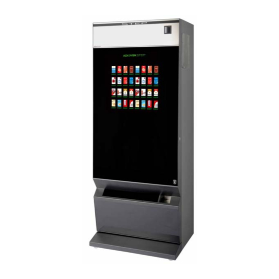
STEP 74
Technical information
Azkoyen STEP 74 Technical Information
Hide thumbs
1
2
3
4
5
6
7
8
9
10
11
12
13
14
15
16
17
18
19
20
21
22
23
24
25
26
27
28
29
30
31
32
33
34
35
36
37
38
39
40
41
42
43
44
45
46
47
48
49
50
51
52
53
54
55
56
57
58
page
of
58
Go
/
58
Bookmarks
Advertisement
Quick Links
Download this manual
Technical Information
S T E P
AZKOYEN
Industrial, S.A.
Avda. San Silvestre, s/n
31350 Peralta (Navarra) Spain
Tel.: +34 948 709 709
www.sat.azkoyen.com
Table of
Contents
Previous
Page
Next
Page
1
2
3
4
5
Advertisement
Need help?
Do you have a question about the STEP 74 and is the answer not in the manual?
Ask a question
Questions and answers
Related Manuals for Azkoyen STEP 74
Vending machines Azkoyen Step Programming Manual
(89 pages)
Vending machines Azkoyen STEP 87 Technical Information
(58 pages)
Vending machines Azkoyen STEP 41 Technical Information
(58 pages)
Vending machines Azkoyen STEP 61 Technical Information
(58 pages)
Vending machines Azkoyen Argenta Programming Manual
(89 pages)
Vending machines Azkoyen PALMA H-70 User Manual
(42 pages)
Vending machines Azkoyen Tempo MI Technical Information
(44 pages)
Vending machines Azkoyen PALMA B Series Technical Manual
(15 pages)
Vending machines Azkoyen Zensia User Manual
Hot drink vending machines (34 pages)
Vending machines Azkoyen ZENSIA Technical Information
(40 pages)
Vending machines Azkoyen TEMPUS III Technical Manual
(79 pages)
This manual is also suitable for:
Step series
Step 87
Step 41
Step 61
Print
Rename the bookmark
Delete bookmark?
Delete from my manuals?
Login
Sign In
OR
Sign in with Facebook
Sign in with Google
Upload manual
Upload from disk
Upload from URL


Need help?
Do you have a question about the STEP 74 and is the answer not in the manual?
Questions and answers