Table of Contents
Advertisement
Quick Links
WARNINGS
• READ AND UNDERSTAND ALL INSTRUCTIONS. Follow all warnings and instructions marked
on the product.
• DISCONNECTED OPTICAL COMPONENTS MAY EMIT INVISIBLE OPTICAL RADIATION THAT
CAN DAMAGE YOUR EYES. TO AVOID SERIOUS INJURY, never look directly into an optical
component that may have a laser coupled to it. If accidental exposure to laser radiation is suspected,
consult a physician for an eye examination.
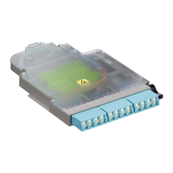
Includes:
1. Splice Module Base (LC or MTP)
2. Splice Module Cover
3. Convertible splice sleeve holder
4. Splice Sleeve Holder retention tabs
5. Single and Ribbon splice sleeves
6. Cable Management tab
7. Cover tab
8. Module Release button
9. Fiber Optic Pigtail
10. Nylon Tie Wraps
11. Mesh Tubing
Optional Accessories:
• HDXAD-ACC - HDX to SDX Adapter Bracket
• 5FUHD-BLK - HDX Adapter Plate Blank
• FSSSD-040 - Single Fiber Splice Sleeves,
40mm (50 pack)
• FSSRB-040 - Ribbon Fiber Splice Sleeves,
40 mm (25 pack)
Installation
1. Open module.
2. Prepare fiber.
Determine termination location. Depending on cable construction, breakout and/or furcation
may be required.
NOTE: Incoming cable opening is 7.6 mm. Evaluate incoming fiber to verify correct sizing.
• High count cable: overall fiber cabling larger than the following requires breakout prior to install:
>36 fiber for MTP splice modules
>12 fiber for LC splice modules
3. Route fiber.
a. Remove at least 35 mm of outer cable jacket.
NOTE: Do not store excessive fiber slack within the module housing. Achieve minimal slack
by routing fiber(s) in the widest path available under the wire management tabs as shown
in the routing diagrams. All other required slack storage should be performed in the fiber
enclosure and/or available pathway outside the enclosure.
b. Feed incoming cable(s) through the rear opening and secure through the tie wrap slots and
over the cable jacket with nylon tie.
4. Prepare pigtail assembly
(single fiber [Option A] or mass fusion [Option B])
NOTE: Cut pigtail after making Zero Mark.
LEG 1
A
BLUE 1
B
ORANGE 2
A
GREEN 3
B
BROWN 4
Option A
A
SLATE 5
B
WHITE 6
A
RED 7
B
BLACK 8
A
YELLOW 9
B
VIOLET 10
A
ROSE 11
B
AQUA 12
LEG 12
1
Option B
12
5. Route pigtail fibers.
a. Route pigtail fibers counter clockwise.
• When splicing single fiber, route the fibers one full loop and mark at Zero Mark.
• When performing mass fusion splices, route the fiber two full loops and mark at Zero Mark.
b. Remove pigtail fibers from module, leaving connectors mated into adapters.
PIGTAIL FIBER
Fiber Pigtail
(Leg 1 of 12)
1
6
OR
4
9
8
LC
Mounts in these devices:
• UHDX Rack Mount Enclosures
• UHDX Rack Mount Panels
• HDX Frame
• SDX Enclosures with HDX to SDX Adapter Brackets
push and lift
250 μm loose tube fiber
900 μm buffered tubing
(VIOLET is shortest)
250 μm loose tube fiber
Approx. 16" (Full loop 25")
MARK FIBER
FOR SPLICING
HDX Splice Module
Cat. Nos. SPLCH, SPMPH
INSTALLATION INSTRUCTIONS
CAUTIONS
• TO AVOID INJURY, wearing safety glasses during installation of this device is recommended. Although
standard safety glasses provide no protection from potential optical radiation, they offer protection from
accidental airborne hardware and cleaning solvents.
• Isopropyl alcohol is flammable and can cause eye irritation on contact. If eye contact occurs, flush with water for
at least 15 minutes. In case of ingestion, consult a physician. Use only in well ventilated areas.
• Fiber optic cable is sensitive to excessive pulling, bending and crushing forces. Do not bend the cable less than
recommended bend radius. Do not use more pulling force than specified. Do not kink or crush the cable.
1
6
4
9
8
MTP
You Will Need:
• Single and/or mass fusion splicer with compatible
fiber holders
• Precision cleaver
• When working with outside plant or armored cables:
- safety blade/utility knife
- armor jacket removing tool
- gel remover
• Tight buffered cable: 12 fiber cable can be routed directly to the splice module. Overall
fiber cabling larger than 7.6 mm, secure the cable to the enclosure cable management tie
down points according to the device instructions, remove the outer jacket after the tie down
point and utilize the mesh sleeve provided in this accessory kit to protect and route the
individual fibers to the module.
• Loose tube cable: if overall fiber cabling larger than 7.6 mm and correctly sub-unitized
under cable jacket, secure cable to tie down points, remove jacket after tie down points and
route sub-unit tubes to each module.
Mark all fiber strands at the
ZERO MARK indicator in the
module base after routing.
ZERO MARK
WHEN TERMINATING
LOOSE TUBE FIBER
6. Route trunk fibers.
a. Route trunk fibers clockwise.
b. Mark all fibers at Zero Mark.
c. Remove all fibers from module.
3
7
5
2
Single Splice sleeves
Ribbon Splice sleeves
x 13 in LC kits
x 1 in LC kits
x 3 in MTP kits
NOTE: Tie wrap will be removed
Cut before
ribbon for loose
tube splicing.
250 μm ribbonized fiber
ZERO MARK
WHEN TERMINATING
RIBBON FIBER
250 μm ribbonized fiber
1
12
ZERO MARK
WHEN TERMINATING
RIBBON FIBER
TRUNK FIBER
(Leg 1- BLUE of 12 shown)
Trunk cable
MARK FIBER
FOR SPLICING
PK-A3258-10-00-0A
ENGLISH
10
x 3
11
x 3
• Fiber termination kit:
- aramid yarn scissors
- lint free wipes
- fiber cleaning solution or 95%
or better isopropyl alcohol
- jacket removing tool
- fiber stripping tool
- fiber waste container
prior to termination.
Tape to
protect while
handling.
1
12
Tape to
protect while
handling.
Incoming
PK-A3258-10-00-0A
Advertisement
Table of Contents

Subscribe to Our Youtube Channel
Related Manuals for Leviton SPLCH


Summary of Contents for Leviton SPLCH
- Page 1 HDX Splice Module Cat. Nos. SPLCH, SPMPH PK-A3258-10-00-0A INSTALLATION INSTRUCTIONS ENGLISH WARNINGS CAUTIONS • READ AND UNDERSTAND ALL INSTRUCTIONS. Follow all warnings and instructions marked • TO AVOID INJURY, wearing safety glasses during installation of this device is recommended. Although on the product.
- Page 2 Leviton warrants to the original consumer purchaser and not for the benefit of anyone else that this product at the time of its sale by Leviton is free of defects in materials and workmanship under normal and proper use for one year from the purchase date. Leviton’s only obligation is to correct such defects by repair or replacement, at its option. For details visit www.leviton.com or call 1-800-824-3005. This warranty excludes and there is disclaimed liability for labor for removal of this product or reinstallation.
Need help?
Do you have a question about the SPLCH and is the answer not in the manual?
Questions and answers