Table of Contents
Advertisement
Advertisement
Table of Contents

Subscribe to Our Youtube Channel
Related Manuals for Alstom EPAC 3100


Summary of Contents for Alstom EPAC 3100
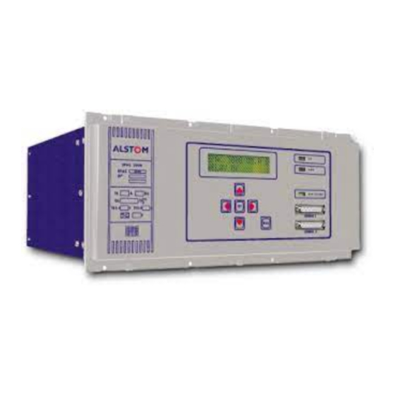
- Page 1 EPAC 3100/3500 Numerical distance relay...
- Page 2 EPAC 3100/3500 Numerical distance relay with integrated automatic and control functions Features • Additional overload, overvoltage • Real time calendar clock of fault reports and oscillography. and undervoltage protection • Fully numerical distance relay functions. • IRIG-B port for real-time clock designed to protect overhead synchronisation.
-
Page 3: Models Available
The relay is fully compatible with the method is used to get the algorithms VT's or CVT's may be on a line or ALSTOM K-range of relays and can to converge rapidly. on busbar side. be integrated into an overall... -
Page 4: Additional Features
• Detection of the 2nd harmonic I>, T> current (inrush current) to protect I>, T> against maloperation due to I>>, T>> I>>, T>> transformer inrush conditions. Z4, T4 Z5, T5 • Fault detection and clearance Z3, T3 during a single-phase cycle in Z2, T2 progress. - Page 5 ANSI/IEE curves IEC curves 1000 1000 Standard inverse Moderately inverse Very inverse Very inverse Extremely Extremely Standard inverse inverse inverse Current (multiple of Is) Current (multiple of Is) 0.0515 0 14 ⋅ Moderately inverse ⋅ Standard inverse 0.114 0.02 0 02 −...
- Page 6 HV network with VT EHV network with CVT Operating Operating Time Time (ms) (ms) SIR=30 (typ) SIR=30 (typ) SIR=30 (max) SIR=30 (max) SIR=1 (typ) SIR=1 (typ) SIR=1 (min) SIR=1 (min) Reach (% ) Reach (% ) Figure 6. Zone 1 50 Hz operating times for phase to neutral faults HV network with VT EHV network with CVT Operating...
-
Page 7: Overload Protection
TPE oscillography: Control system: current loop connection to UR K-Bus courier (data concentrator) or VDEW or modem connection Daughter boards Rear panel IRIG-B - oscillography - protection logic Analogue - setting groups - measurement board Power algorithms supply 12 bits ADC IRIG.B INTEL 960 TMS 320 C25... -
Page 8: Hardware Description
Configuration Each fault report includes time • 16-bit sampling of current values tagged details of the faulted phases, and 12-bit sampling of voltage Inputs and outputs values. trip type and fault location (fault distance and apparent resistance). • 8 or 16 user programmable, •... -
Page 9: Maintenance Software
Figure 14. Rear panel and K-bus connection to the terminal block Maintenance software Relay 32 Relay 4 Relay 3 Relay 2 Relay 1 WinEPAC software also includes a commissioning and maintenance program to facilitate commissioning tests and providing guidance for maintenance personnel. - Page 10 C.T. Shorting links make before [b] disconnect Short terminals Pin terminal [P.C.Btype] Terminal block 27 28 50 Ohm BNC connector Output contact Opto-isolated input 27X6 Phase A voltage 28X6 V.T. secondaries Phase rotation Phase B voltage Case earth Direction of power flow for operation K-Bus connection can Phase C voltage be either way...
-
Page 11: Technical Data
Technical Data Settings Line parameters Ratings Neutral earthing direct Inputs isolated or Petersen coil earthed network AC current (In) 1 A and 5 A Length of line in km or miles 0.3 to 999.99 km or 0.18 to 621.49 miles AC voltage (Vn) 100 V to 120 V in steps of 1V steps of 0.01... - Page 12 Unblocking on residual current Ir yes/no Reversal guard extension Unblocking percentage threshold kr 10 to 100% Reverse locking extension time-delay 0 to 150 ms in steps of 1 % of Ir in steps of 10 ms Unblocking on overcurrent Imax yes/no Fault locator Unblocking threshold Imax...
- Page 13 Zero sequence active power protection Electro-magnetic compatibility IEC 255-22 High frequency disturbance (255-22-1) 2.5 kV peak between independent circuits and Zero sequence active power yes/no case Secondary current for max. angle error of current transformer 1 mA to 4 A 1.0 kV peak across terminals of the same circuit in steps of 1 mA Electrostatic discharge (255-22-1)
-
Page 14: Information Required With Order
Information required with order EPAC 3111/3511 EPAC 3112/3512 EPAC 3113/3513 EPAC 3116/3516 EPAC 3121/3521 EPAC 3122/3522 EPAC 3123/3523 EPAC 3126/3526 EPAC 3131/3531 EPAC 3132/3532 EPAC 3133/3533 EPAC 3136/3536 Case: Flush panel Rack Language: French English German Spanish Auxiliary voltage: 48 Vdc 60 Vdc 110 Vdc 125 Vdc... -
Page 15: Additional Information
Glossary 483.00 465.10 Courier: A communication 304.30 language developed to provide 88.90 generic control, monitoring, data 101.60 151.50 extraction and setting changes on 57.10 37.70 remote devices (primarily on 15.50 Front view for rack mounting Side view protective relays) within the substation evironment. - Page 16 ALSTOM T&D Protection & Contrôle - 95, rue de la Banquière - BP 75 - 34975 Lattes Cedex FRANCE Tél : 33 (0)4 67 20 54 54 - Télex : 485 093 F - Fax : 33 (0)4 67 20 54 99 - E-mail: protection.controle@tde.alstom.com...
Need help?
Do you have a question about the EPAC 3100 and is the answer not in the manual?
Questions and answers