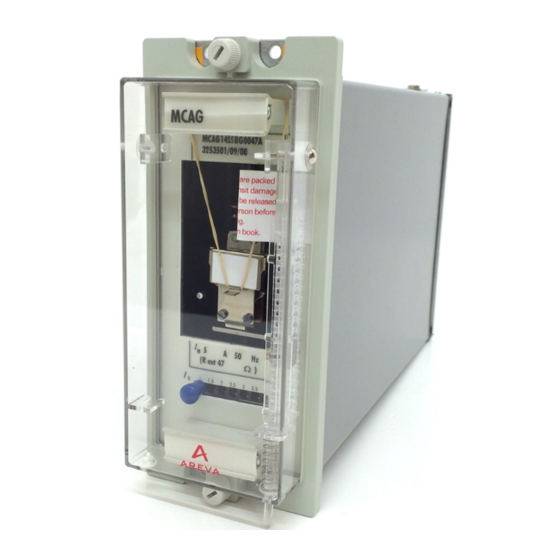
Alstom MCAG User Manual

Alstom MCAG User Manual

Application of high impedance relays

Advertisement

R6136C © 2012. ALSTOM, the ALSTOM logo and any alternative version thereof are trademarks and service marks of ALSTOM. The other names mentioned,
registered or not, are the property of their respective companies. The technical and other data contained in this document is provided for information only. Neither
ALSTOM, its officers or employees accept responsibility for, or should be taken as making any representation or warranty (whether express or implied), as to the
accuracy or completeness of such data or the achievement of any projected performance criteria where these are indicated. ALSTOM reserves the right to revise or
change this data at any time without further notice.
MCAG/MFAC
User Guide
Application of High Impedance Relays
Publication Reference:
R6136C
GRID

Advertisement

Table of Contents
loading
Need help?

Need help?

Do you have a question about the MCAG and is the answer not in the manual?

Questions and answers

Summary of Contents for Alstom MCAG

  • Page 1 GRID ALSTOM, its officers or employees accept responsibility for, or should be taken as making any representation or warranty (whether express or implied), as to the accuracy or completeness of such data or the achievement of any projected performance criteria where these are indicated. ALSTOM reserves the right to revise or...
  • Page 2 1 and current transformer saturation with through fault current condition. formula 2 for the MCAG/MFAC all applications. and MCTI respectively. The setting It can be seen from Figure 1, that will be dependent upon the...
  • Page 3 ). This relationship can be than twice the relay voltage setting secondary respectively. In ≥ 2V expressed in three ways: i.e. V for the MCAG/MFAC applications such as busbar and 1.6V for the MCTI. protection, where higher values of To determine the maximum current...
  • Page 4 required stability voltage setting (V as in busbar protection, it is always When the value given by the and the relay current setting ( advisable to use a non-linear resistor formulae is greater than 3000V (metrosil) across the relay circuit peak, non-linear resistors (metrosils) (relay and stabilising resistor).
  • Page 5 At the maximum secondary current, Setting range: 25-175V the non-linear resistor (metrosil) Setting Voltage should limit the voltage to 1500V r (mA) rms or 2120V peak for 0.25 second. At higher relay voltage Setting range: 25-325V Setting Voltage settings, it is not always possible to r (mA) limit the fault voltage to 1500V rms, so higher fault voltages may have to...
  • Page 6 Figure 4: Balanced or restricted earth fault protection for delta winding of a power transformer with supply system earthed Figure 5: Restricted earth fault protection for 3 phase, 4 wire system-applicable to star connected generators or power transformer windings with neutral earthed at switchgear Figure 6: Restricted earth fault protection for 3 phase 4 wire system applicable to star connected generators or power transformer windings earthed directly at the star point...
  • Page 7 Figure 7: Phase and earth fault differential protection for an auto-transformer with CT’s at the neutral star point Figure 8: Busbar protection – simple single zone phase and earth fault scheme...
  • Page 8 Typical setting examples + 2R As previously stated metrosils are always required with an MFAC. The = 27820 x 5 (0.3 + 0.08) Restricted earth fault metrosil type is chosen in 1 500 protection using MFAC14 accordance with the maximum = 35.2V secondary current of 27820 x 5/ The correct application of the...
  • Page 9 The exciting current to be drawn by This value is well below the Stability voltage the current transformers at the relay maximum of 3000V peak and The power transformer full load stability voltage, V , will be: therefore no metrosils are required current with the relay.
  • Page 10 should be connected across the The relatively low level of current Stabilising resistor relay and stabilising resistor, in that is delivered by a generator to Assuming that the relay effective order to protect the insulation of the an external fault means that stability setting for a solidly earthed power current transformers, relay and of high impedance generator...
  • Page 11 = 0.1A = 7.98A Figure 10: Generator winding differential protection Stabilising resistor Current transformer Metrosil non-linear resistor requirements requirements The minimum current transformer If the peak voltage appearing kneepoint voltage across the relay circuit under maximum internal fault conditions 2.55 - 1 = 2V exceeds 3000V peak then a = 2 x 10...
  • Page 12 PXXX Product Description Alstom Grid © - ALSTOM 2011. ALSTOM, the ALSTOM logo and any alternative version thereof are trademarks and service marks of ALSTOM. The other names mentioned, registered or not, are the property of their respective companies. The technical and other data contained in this document is provided for information only.

This manual is also suitable for:

Mfac

Table of Contents

Save PDF