Table of Contents
Advertisement
© - ALSTOM 2014. All rights reserved. Information contained in this document is indicative only. No representation or warranty is given or should be relied on that it
is complete or correct or will apply to any particular project. This will depend on the technical and commercial circumstances. It is provided without liability and is
subject to change without notice. Reproduction, use or disclosure to third parties, without express written authority, is strictly prohibited.
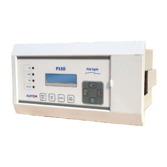
MiCOM P50 Agile P15D
Technical Manual
Dual Powered overcurrent relay
Platform Hardware Version: A
Platform Software Version: 01
Publication Reference:
P15D/EN M/B
Advertisement
Chapters
Table of Contents

Related Manuals for Alstom MiCOM P50 Agile P15D


Summary of Contents for Alstom MiCOM P50 Agile P15D
- Page 1 P15D/EN M/B © - ALSTOM 2014. All rights reserved. Information contained in this document is indicative only. No representation or warranty is given or should be relied on that it is complete or correct or will apply to any particular project. This will depend on the technical and commercial circumstances. It is provided without liability and is...
- Page 3 P50 Agile P15D 1 Introduction INTRODUCTION CHAPTER 1 P15D/EN TM/B...
- Page 4 P50 Agile P15D 1 Introduction P15D/EN TM/B...
- Page 5 P50 Agile P15D 1 Introduction CHAPTER OVERVIEW This chapter consists of the following sections: Chapter Overview Introduction Features Functional Overview Ordering information P15D/EN TM/B...
- Page 6 P50 Agile P15D 1 Introduction INTRODUCTION Features The P15D is a dual powered non-directional overcurrent and earth fault relay which provides protection for applications where no external auxiliary power supply is available, or where the auxiliary supply available does not guarantee the dependability required for protection applications. This relay is mainly deployed in industrial installations, distribution network substations and most specifically in Ring Main Unit (RMU) networks for monitoring and protection purposes.
- Page 7 P50 Agile P15D 1 Introduction Communications Front USB port for real-time data viewing, device setting, and upload/download. Rear EIA (RS) 485 port for SCADA communication Multiple protocols - Modbus/ IEC60870-5-103 (user selectable) Functional Overview ANSI FUNCTION P15D Definite time overcurrent ...
- Page 8 P50 Agile P15D 1 Introduction Ordering information Figure 1: Ordering Information P15D/EN TM/B...
- Page 9 SAFETY INFORMATION CHAPTER 2 ...
- Page 10 Safety Information Pxxx...
- Page 11 Pxxx Safety Information HEALTH AND SAFETY Personnel associated with the equipment must be familiar with the contents of this Safety Information. When electrical equipment is in operation, dangerous voltages are present in certain parts of the equipment. Improper use of the equipment and failure to observe warning notices will endanger personnel. Only qualified personnel may work on or operate the equipment.
- Page 12 Safety Information Pxxx SYMBOLS Throughout this manual you will come across the following symbols. You will also see these symbols on parts of the equipment. Caution: Refer to equipment documentation. Failure to do so could result in damage to the equipment Warning: Risk of electric shock Earth terminal.
- Page 13 Pxxx Safety Information INSTALLATION, COMMISSIONING AND SERVICING LIFTING HAZARDS Many injuries are caused by: ● Lifting heavy objects ● Lifting things incorrectly ● Pushing or pulling heavy objects ● Using the same muscles repetitively Plan carefully, identify any possible hazards and determine how best to move the product. Look at other ways of moving the load to avoid manual handling.
- Page 14 Safety Information Pxxx Caution: NEVER look into optical fibres or optical output connections. Always use optical power meters to determine operation or signal level. Caution: Testing may leave capacitors charged to dangerous voltage levels. Discharge capacitors by rediucing test voltages to zero before disconnecting test leads. Caution: Operate the equipment within the specified electrical and environmental limits.
- Page 15 Pxxx Safety Information Caution: Where UL/CSA listing of the equipment is not required, a high rupture capacity (HRC) fuse type with a maximum current rating of 16 Amps and a minimum dc rating of 250 V dc may be used for the auxiliary supply (for example Red Spot type NIT or TIA).
- Page 16 Safety Information Pxxx PROTECTION CLASS 1 EQUIPMENT REQUIREMENTS Caution: Earth the equipment with the supplied PCT (Protective Conductor Terminal). Caution: Do not remove the PCT. Caution: The PCT is sometimes used to terminate cable screens. Always check the PCT’s integrity after adding or removing such earth connections. Caution: Use a locknut or similar mechanism to ensure the integrity of stud-connected PCTs.
- Page 17 CT before opening any connections to it. Note: For most Alstom equipment with ring-terminal connections, the threaded terminal block for current transformer termination is automatically shorted if the module is removed. Therefore external shorting of the CTs may not be required.
- Page 18 Safety Information Pxxx DECOMMISSIONING AND DISPOSAL Caution: Before decommissioning, completely isolate the equipment power supplies (both poles of any dc supply). The auxiliary supply input may have capacitors in parallel, which may still be charged. To avoid electric shock, discharge the capacitors using the external terminals before decommissioning.
- Page 19 Pxxx Safety Information STANDARDS COMPLIANCE Compliance with the European Commission Directive on EMC and LVD is demonstrated using a Technical File. EMC COMPLIANCE: 2004/108/EC Compliance with EN60255-26:2009 was used to establish conformity. PRODUCT SAFETY: 2006/95/EC Compliance with EN60255-27:2005 was used to establish conformity. Protective Class IEC 60255-27: 2005 Class 1 (unless otherwise specified in equipment documentation).
- Page 20 Safety Information Pxxx Equipment with this marking is not itself suitable for operation within a potentially explosive atmosphere. Compliance demonstrated by Notified Body Type Examination Certificate. ATEX Potentially Explosive Atmospheres directive 94/9/EC for equipment.
- Page 21 P50 Agile P15D 3 Hardware Design HARDWARE DESIGN CHAPTER 3 P15D/EN TM/B...
- Page 22 P50 Agile P15D 3 Hardware Design P15D/EN TM/B...
- Page 23 P50 Agile P15D 3 Hardware Design CHAPTER OVERVIEW This chapter consists of the following sections: Chapter Overview Hardware Design Overview of Hardware design Micro controller with DSP module 2.2.1 Micro Controller Module (Processor board) Analogue input module Power supply module P15D/EN TM/B...
- Page 24 P50 Agile P15D 3 Hardware Design HARDWARE DESIGN The P15D hardware comprises of following main components:- • The housing, consisting of a front panel and connections at the rear • Micro controller with DSP module • Analogue input circuit • Digital input circuit •...
- Page 25 P50 Agile P15D 3 Hardware Design The CPU design is a hybrid of the digital signal processor (DSP) and high speed micro controller which runs complex algorithm for deriving the fundamental & harmonic component from the input current signals. The digital inputs and outputs modules are designed to interface the monitoring, control and protection signals through optically isolated circuit as per the field requirements.
- Page 26 P50 Agile P15D 3 Hardware Design Micro controller with DSP module Digital Processing Circuit consists of a high speed DSP controller. The high speed DSP controller continuously monitors line phase current and E/F current through CTs, along with different optical isolated status connections.
- Page 27 P50 Agile P15D 3 Hardware Design 5 V O/P Current To relay electronics Transformer 24 V O/P to Tripping Output Auxiliary Supply Module External Battery P5004ENa Figure 3: Block Diagram of Power Supply Module P15D/EN TM/B...
- Page 28 P50 Agile P15D 3 Hardware Design P15D/EN TM/B...
- Page 29 P50 Agile P15D 4 Front Panel FRONT PANEL CHAPTER 4 P15D/EN TM/B...
- Page 30 P50 Agile P15D 4 Front Panel P15D/EN TM/B...
- Page 31 P50 Agile P15D 4 Front Panel CHAPTER OVERVIEW This chapter consists of the following sections: Chapter Overview front panel User Interface 2.1.1 LCD Display 2.1.2 Touch Keys 2.1.3 LEDs 2.1.4 RS 485 Port 2.1.5 USB Port P15D/EN TM/B...
- Page 32 P50 Agile P15D 4 Front Panel FRONT PANEL Figure 1: Front panel SL no Label Function The green LED indicates that the power is ‘ON’. (Required ≥20% of load Current) & blinking green LED indicates ‘Trip Block function’ is enabled or the relay is ‘OUT OF SERVICE’. START The amber LED is the Relay ‘START’...
- Page 33 P50 Agile P15D 4 Front Panel SL no Label Function USB Port USB Communication Port. (access to the USB communication port underneath the cover) Battery Capacity 4.5Volt (1.5 x 3) AA non-rechargeable battery. (access to the Battery underneath the cover) User Interface 2.1.1 LCD Display...
- Page 34 P50 Agile P15D 4 Front Panel 2.1.3 LEDs The P15D Relay has 4 high-intensity LEDs for easy identification of fault type for easy user interface. SL no Label Function LED 1 The green LED indicates that the power is ‘ON’. (Required ≥20% of load Current) & green LED indicates ‘Trip Block function’...
- Page 35 P50 Agile P15D 4 Front Panel Figure 2: USB Port P15D/EN TM/B...
- Page 36 P50 Agile P15D 4 Front Panel P15D/EN TM/B...
- Page 37 P50 Agile P15D 5 Configuration CONFIGURATION CHAPTER 5 P15D/EN TM/B...
- Page 38 P50 Agile P15D 5 Configuration P15D/EN TM/B...
- Page 39 P50 Agile P15D 5 Configuration CHAPTER OVERVIEW This chapter consists of the following sections: Chapter Overview Configuration Changing the settings Procedure for changing the setting of Parameters 2.2.1 General procedure for changing setting of any parameter (with alphabetic value) 2.2.2 General procedure for changing setting of any parameter (with numerical value) MENUS 2.3.1...
- Page 40 P50 Agile P15D 5 Configuration 2.3.15.2 Edit settings (For I>1, IEC or IEEE Curves are selected) 2.3.15.3 Edit settings (For I>1, DT i.e. Definite Time is selected) 2.3.16 GROUP 1 - Under Current Protection SUB MENU 2.3.16.1 Edit settings (if I< Status is set as Disabled) 2.3.16.2 Edit Settings (if I<...
- Page 41 P50 Agile P15D 5 Configuration 2.4.18 Edit/View Records menu 2.4.18.1 View Fault Record 2.4.18.2 View Error Log: P15D/EN TM/B...
- Page 42 P50 Agile P15D 5 Configuration CONFIGURATION Each product has different configuration parameters according to the functions it has been designed to perform. There is, however, a common methodology used across the entire product to set these parameters. This chapter describes an overview of this common methodology, as well as providing concise instructions of how to configure the device.
- Page 43 P50 Agile P15D 5 Configuration Changing the settings The general procedure for changing settings is explained with an example: Example: Changing setting for Trip Test function Step 1: Select CB CONTROL Menu CB CONTROL Press the Left arrow key ( ). And password window will appear Step 2 : Password 0001...
- Page 44 P50 Agile P15D 5 Configuration Step 8: After changing the settings, press the Edit Key. The text will then stop blinking and display the following: Trip Test Enabled Press the Left arrow key ( ). It will ask if you want to save the setting, and display the Step 9: following: SET For Save...
- Page 45 P50 Agile P15D 5 Configuration Procedure for changing the setting of Parameters 2.2.1 General procedure for changing setting of any parameter (with alphabetic value) Step 1: Press the Edit Key the first alphabet of word will start blinking Trip Test and shall be displayed as follows.
- Page 46 P50 Agile P15D 5 Configuration 2.2.2 General procedure for changing setting of any parameter (with numerical value) Step 1: Press the Edit Key the last digit of the number will start blinking Password = 0000 and shall be displayed as follows. By using the left arrow key ( ) the blinking (number) selection can be shifted from right to left.
- Page 47 P50 Agile P15D 5 Configuration This window will flash momentarily showing the following OC/EF Relay Relay Type: OC/EF Relay Software Version: V1.03 Unit ID = 001 ID = 001 V1.03 Then the control will go automatically to default window This window shows actual Primary load current as per the CT Primary A=0000 A selection.
- Page 48 P50 Agile P15D 5 Configuration Password protected window for “RECORD CONTROL’’ setting i.e. Clear RECORD CONTROL Events, Clear Maint, Clear Dist Rec, Clear Faults and Reset Thermal State. Press the Plus / up arrow key (+ /) to move to the next option. Password protected window for “COMMUNICATION’’...
- Page 49 P50 Agile P15D 5 Configuration This window shows actual Primary load current as per the CT Primary A=0000 A selection. Press the Plus / right arrow key (+ /) to move to the next option. B=0000 A This window shows actual Primary load current as per the CT Primary C=0000 A selection.
- Page 50 P50 Agile P15D 5 Configuration Press the Edit Key, the text will start blinking. Trip Test By using the Plus / Up arrow key (+ /) or the Minus / Right arrow key (- /) the desired Trip Test can set i.e. Enabled or Disabled. Enabled After selecting the desired Trip Test press the Edit Key, the text will stop blinking.
- Page 51 P50 Agile P15D 5 Configuration 2.3.4.2 View settings Press the Minus / Right arrow key (- /) to view the CB Control settings. CB CONTROL This window shows the Trip Test setting done previously. Trip Test Press the Plus / Up arrow key (+ /) to move to the next option. *** Enabled This window shows the Trip Block setting done previously.
- Page 52 P50 Agile P15D 5 Configuration Press the Edit Key, the number will start blinking. Password = 0000 Enter the previously set password by using the Plus / Up arrow key (+ /) or the Minus / Right arrow key (- /). The Password setting range is 0000 to 9999.
- Page 53 P50 Agile P15D 5 Configuration Press the Edit Key, the text will start blinking. DST Start Day By using the Plus / Up arrow key (+ /) or the Minus / Right arrow key (- /) the desired DST Start Day can set i.e. Sunday to Saturday. Sunday After selecting the desired DST Start Day press the Edit Key, the text will stop blinking.
- Page 54 P50 Agile P15D 5 Configuration Press the Edit Key, the number will start blinking. DST End mins By using the Plus / Up arrow key (+ /) or the Minus / Right arrow key (- /) the desired DST End minutes can be set. The setting range is from 0060 Mins 0000 to 1425 in steps of 15.
- Page 55 P50 Agile P15D 5 Configuration Press the Edit Key, the number will start blinking. SET Month By using the Plus / Up arrow key (+ /) or the Minus / Right arrow key (- /) the desired SET Month can be set. The setting range is from 1 to 12 in steps of 1.
- Page 56 P50 Agile P15D 5 Configuration Note: The User can scroll the previous settings by using the Plus / Up arrow key (+ / ** After Editing any sub menus of the DATE AND TIME setting, If the SET/ Left ( ) arrow key is pressed, the Relay ask SET to SAVE the changes or RESET to CANCEL the changes.
- Page 57 P50 Agile P15D 5 Configuration This window shows the DST Start Day setting done previously. DST Start Day Press the Plus / Up arrow key (+ /) to move to the next option. *** Sunday This window shows the DST Start Month setting done previously. DST Start Month Press the Plus / Up arrow key (+ /) to move to the next option.
- Page 58 P50 Agile P15D 5 Configuration DATE AND TIME Note: *** By using the Left arrow key ( ) or Right arrow key ( ) the relay will return to Main Menu. 2.3.6 CONFIGURATION MENU 2.3.6.1 Edit settings Password protected window for “CONFIGURATION” settings i.e. CONFIGURATION Restore Defaults, Active Settings, Setting Group1, Setting Group 2, System Configuration, Over Current, Earth Fault, Thermal Overload,...
- Page 59 P50 Agile P15D 5 Configuration Press the Edit Key, the text will start blinking. Setting Group 1 By using the Plus / Up arrow key (+ /) or the Minus / Right arrow key (- /) the desired Setting Group 1 can set i.e. Enabled or Disabled. Enabled After selecting the desired Setting Group 1 press the Edit Key, the text will stop blinking.
- Page 60 P50 Agile P15D 5 Configuration Press the Edit Key, the text will start blinking. Cold Load Pickup By using the Plus / Up arrow key (+ /) or the Minus / Right arrow key (- /) the desired Cold Load Pickup can set i.e. Enabled or Disabled. Enabled After selecting the desired Cold Load Pickup press the Edit Key, the text will stop blinking.
- Page 61 P50 Agile P15D 5 Configuration Note: The User can scroll the previous settings by using the Plus / Up arrow key (+ / ** After Editing any sub menus of the CONFIGURATION setting, If the SET/ Left ( ) arrow key is pressed, the Relay ask SET to SAVE the changes or RESET to CANCEL the changes.
- Page 62 P50 Agile P15D 5 Configuration This window shows the Earth Fault setting done previously. Earth Fault Press the Plus / Up arrow key (+ /) to move to the next option. *** Enabled This window shows the Thermal Overload setting done previously. Thermal Overload Press the Plus / Up arrow key (+ /) to move to the next option.
- Page 63 P50 Agile P15D 5 Configuration 2.3.7 CT & VT RATIOS MENU 2.3.7.1 Edit settings Password protected window for “CT AND VT RATIOS settings i.e. CT AND VT RATIOS Phase CT Primary and E/F CT Primary. Press the Left arrow key () to move to the next option.
- Page 64 P50 Agile P15D 5 Configuration CT AND VT RATIOS Note: The User can scroll the previous settings by using the Plus / Up arrow key (+ / ** After editing any sub menus of the CT AND VT RATIOS setting, If the SET/ Left ( ) arrow key is pressed, the Relay ask SET to SAVE the changes or RESET to CANCEL the changes.
- Page 65 P50 Agile P15D 5 Configuration CT AND VT RATIOS Note: *** By using the Left arrow key ( ) or Right arrow key ( ) the relay will return to Main Menu. 2.3.8 RECORD CONTROL MENU 2.3.8.1 Edit settings Password protected window for “RECORD CONTROL”...
- Page 66 P50 Agile P15D 5 Configuration Press the Edit Key, the text will start blinking. Clear Maint By using the Plus / Up arrow key (+ /) or the Minus / Right arrow key (- /) the desired Clear Maintenance Records can set i.e. Yes / No. After selecting the desired Clear Maint press the Edit Key, the text will stop blinking.
- Page 67 P50 Agile P15D 5 Configuration 2.3.9 COMMUNICATION MENU 2.3.9.1 Edit settings Password protected window for “COMMUNICATION” settings i.e. RP1 COMMUNICATION Address, RP1 Baudrate, RP1 Parity and RP1 Timesync. Press the Right arrow key () to move to the next option. Press the Edit Key, the number will start blinking.
- Page 68 P50 Agile P15D 5 Configuration The window displays the first setting of the Communication Menu. RP1 Address Press the Left arrow key () the relay show as follows Press the SET / Left arrow key () to SAVE the changes. SET For Save Press the RESET key to CANCEL the changes..
- Page 69 P50 Agile P15D 5 Configuration This window shows the RP1 Parity setting done previously. RP1 Parity Press the Plus / Up arrow key (+ /) to move to the next option. *** Even This window shows the RP1 Timesync setting done previously. RP1 Timesync Press the Plus / Up arrow key (+ /) to move to the next option.
- Page 70 P50 Agile P15D 5 Configuration Password protected window for “SYSTEM CONFIGURATION” settings. SYSTEM CONFIG Password protected window for “OVERCURRENT” Protection settings. OVERCURRENT Password protected window for “EARTH FAULT” Protection settings. EARTH FAULT Password protected window for “THERMAL OVERLOAD” Protection THERMAL OVER LOAD settings.
- Page 71 P50 Agile P15D 5 Configuration Press the SET / Left arrow key () to SAVE the changes. SET For Save Press the RESET key to CANCEL the changes. RESET For Cancel When the SET / Left arrow key () is pressed the relay will SAVE the changes and this window will flash for moment.
- Page 72 P50 Agile P15D 5 Configuration Press the SET / Left arrow key () to SAVE the changes. SET For Save Press the RESET key to CANCEL the changes. RESET For Cancel When the SET / Left arrow key () is pressed the relay will SAVE the changes and this window will flash for moment.
- Page 73 P50 Agile P15D 5 Configuration Press the SET / Left arrow key () to SAVE the changes. SET For Save Press the RESET key to CANCEL the changes. RESET For Cancel When the SET / Left arrow key () is pressed the relay will SAVE the changes and this window will flash for moment.
- Page 74 P50 Agile P15D 5 Configuration Press the Edit Key, the number will start blinking. I>1 tRESET By using the Plus / Up arrow key (+ /) or the Minus / Right arrow key (- /) the desired I>1 tRESET can be set. The setting range is from 001.00 000.00 to 100.00 in steps of 0.01.
- Page 75 P50 Agile P15D 5 Configuration 2.3.12.3 Edit settings (if I>1 function is selected for IEEE Curves) By using the Plus / Up arrow key (+ /) or Minus / Right arrow key (- Overcurrent /) select the Over Current setting menu in Group 1. Press the Left arrow key () to move to the next option.
- Page 76 P50 Agile P15D 5 Configuration Press the Edit Key, the number will start blinking. I>1 Time Dial By using the Plus / Up arrow key (+ /) or the Minus / Right arrow key (- /) the desired I>1 Time Dial can be set. The setting range is from 001.00 000.01 to 100.00 in steps of 0.01.
- Page 77 P50 Agile P15D 5 Configuration Note: If the function is set as enable then the relay will allow editing the settings of respective sub menus. If the function is set as disable then the relay will not allow editing the settings of sub menus and will bypass the protection function.
- Page 78 P50 Agile P15D 5 Configuration Press the Edit Key, the number will start blinking. I>1 tRESET By using the Plus / Up arrow key (+ /) or the Minus / Right arrow key (- /) the desired I>1 tRESET can be set. The setting range is from 001.00 000.00 to 100.00 in steps of 0.01.
- Page 79 P50 Agile P15D 5 Configuration The settings of I>2 Function and I>3 Function to be set in similar manner as that of I>1 Function. 2.3.13 GROUP 1 EARTH FAULT SUB MENU 2.3.13.1 Edit settings (if IN>1 function is disabled) By using the Plus / Up arrow key (+ /) or Minus / Right arrow key (- Earth Fault /) select the Earth Fault setting menu in Group 1.
- Page 80 P50 Agile P15D 5 Configuration 2.3.13.2 Edit settings (if IN>1 function is selected for IEC curves) By using the Plus / Up arrow key (+ /) or Minus / Right arrow key (- Earth Fault /) select the Earth Fault setting menu in Group 1. Press the Left arrow key () to move to the next option.
- Page 81 P50 Agile P15D 5 Configuration The window displays the first setting of the Earth Fault setting menu. IN>1Current Set Press the Left arrow key () to move to the next option. 0.20 A Press the SET / Left arrow key () to SAVE the changes. SET For Save Press the RESET key to CANCEL the changes.
- Page 82 P50 Agile P15D 5 Configuration Press the Edit Key, the number will start blinking. IN>1Current Set By using the Plus / Up arrow key (+ /) or the Minus / Right arrow key (- /) the desired IN>1 Current Setting can be set. The setting range is 0.20 A from 0.10 to 2.50 in steps of 0.01.
- Page 83 P50 Agile P15D 5 Configuration GROUP 1 Note: #. If the function is set as enable then the relay will allow editing the settings of respective sub menus. If the function is set as disable then the relay will not allow editing the settings of sub menus and will bypass the protection function.
- Page 84 P50 Agile P15D 5 Configuration Press the Edit Key the number will start blinking. IN>1 Time Delay By using the Plus / Up arrow key (+ /) or the Minus / Right arrow key (- /) the desired IN>1 Time Delay can be set. The setting range is from 001.00 000.00 to 200.00 in steps of 0.01.
- Page 85 P50 Agile P15D 5 Configuration Note: #. If the function is set as enable then the relay will allow editing the settings of respective sub menus. If the function is set as disable then the relay will not allow editing the settings of sub menus and will bypass the protection function.
- Page 86 P50 Agile P15D 5 Configuration GROUP 1 Note: #. If the function is set as enable then the relay will allow editing the settings of respective sub menus. If the function is set as disable then the relay will not allow editing the settings of sub menus and will bypass the protection function.
- Page 87 P50 Agile P15D 5 Configuration Press the Edit Key, the number will start blinking. Time Constant 1 By using the Plus / Up arrow key (+ /) or the Minus / Right arrow key (- /) the desired Time Constant 1 can be set. The setting range is from 001.00 001 to 200 in steps of 1.
- Page 88 P50 Agile P15D 5 Configuration 2.3.15 GROUP 1 -COLD LOAD PICKUP SUB MENU 2.3.15.1 Edit settings (Protection Menu) By using the Plus / Up arrow key (+ /) or Minus / Right arrow key (- Cold Load Pickup /) select the Cold Load Pickups setting menu in Group 1. Press the Left arrow key () to move to the next option.
- Page 89 P50 Agile P15D 5 Configuration Press the Edit Key, the text will start blinking. I>3 Status By using the Plus / Up arrow key (+ /) or the Minus / Right arrow key (- /) the desired I>3 Status can be set i.e. Enable / Block. # Enable After selecting the desired I>1 Status press the Edit Key, the text will stop blinking.
- Page 90 P50 Agile P15D 5 Configuration Note: #. If the function is set as enabled then the relay will allow editing the settings of respective sub menus. If the function is set as disabled then the relay will not allow editing the settings of sub menus and will bypass the protection function.
- Page 91 P50 Agile P15D 5 Configuration Press the Edit Key, the number will start blinking. I>1 Current Set By using the Plus / Up arrow key (+ /) or the Minus / Right arrow key (- /) the desired I>1 Current Set can be set. The setting range is from 1.50 A 0.20 to 4.00 in steps of 0.01.
- Page 92 P50 Agile P15D 5 Configuration 2.3.15.3 Edit settings (For I>1, DT i.e. Definite Time is selected) By using the Plus / Up arrow key (+ /) or Minus / Right arrow key (- Cold Load Pickup /) select the Cold Load Pickup setting menu in Group 1. Press the Left arrow key () to move to the next option.
- Page 93 P50 Agile P15D 5 Configuration Press the SET / Left arrow key () to SAVE the changes. SET For Save Press the RESET key to CANCEL the changes. RESET For Cancel When the SET / Left arrow key () is pressed the relay will SAVE the changes and this window will flash for moment.
- Page 94 P50 Agile P15D 5 Configuration Press the Edit Key, the text will start blinking. I< Status By using the Plus / Up arrow key (+ /) or the Minus / Right arrow key (- /) the desired I< Status can be set i.e. Enable / Disable # Disabled After selecting the desired I<...
- Page 95 P50 Agile P15D 5 Configuration Press the Edit Key, the number will start blinking. I< By using the Plus / Up arrow key (+ /) or the Minus / Right arrow key (- /) the desired I< settings can be set. The setting range is from 0.10 to 1.00 A 1.00 in steps of 0.01.
- Page 96 P50 Agile P15D 5 Configuration 2.3.17 GROUP 2 MENU 2.3.17.1 Edit settings Password protected window for “GROUP 2” settings i.e. System GROUP 2 Configuration, Over Current, Earth Fault, Thermal Overload, Cold Load Pickup and Under Current Protection. Press the Left arrow key () the relay will display as follows. Press the Edit Key, the number will start blinking.
- Page 97 P50 Agile P15D 5 Configuration Password protected window for “UNDERCURRENT” Protection settings UNDERCURR PROT Note: The Group 2 Function for the setting System Configuration, over Current, Earth Fault, Thermal Overload, Cold Load Pkp and under Current Protection is similar to Group 1. 2.3.18 SYSTEM DATA MENU 2.3.18.1...
- Page 98 P50 Agile P15D 5 Configuration Press the SET / Left arrow key () to SAVE the changes. SET For Save Press the RESET key to CANCEL the changes. RESET For Cancel When the SET / Left arrow key () is pressed the relay will SAVE the changes and this window will flash for moment.
- Page 99 P50 Agile P15D 5 Configuration This window shows the Serial number of the relay. Serial Number Press the Plus / Up arrow key (+ /) to move to the next option. *** 14EP15D0001 This window shows the software version of the relay. Software Version Press the Plus / Up arrow key (+ /) to move to the next option.
- Page 100 P50 Agile P15D 5 Configuration This window shows latch relay status. RLY O/P STATUS Press the Plus / Up arrow key (+ /) to move to the next option. *** LATCH RLY = OFF The window displays the first setting of System Data. Language Press the Left arrow key () or Right arrow key () to return to the Main Menu.
- Page 101 P50 Agile P15D 5 Configuration This window will show trip flag of under current operated. Undercurr Flt Press the Plus / Up arrow key (+ /) to move to the next option. *** I<: This window will show Trip Counter. Trip Counter Press the Plus / Up arrow key (+ /) to move to the next option.
- Page 102 P50 Agile P15D 5 Configuration 2.3.19.2 View Error Log By using the Plus / Up arrow key (+ /) or Minus / Right arrow key (- VIEW RECORDS /) select the View Records setting menu. Press the Right arrow key (- /) to move to the next option. This window shows the Fault Record Fault Record Press the Plus / Up arrow key (+ /) to move to the next...
- Page 103 P50 Agile P15D 5 Configuration Configuration flowcharts 2.4.1 Main Menu After the Power ON or when the relay is reset the following windows will be displayed, and the user can scroll through the main menu as below. A=0000 A P50 Agile P15D OC/EF Relay ID=001 V0.10 B=0000 A...
- Page 104 P50 Agile P15D 5 Configuration 2.4.2 View Measurement menu MEASUREMENTS A=0000 A B=0000 A C=0000 A N=0000 A A=00.00 A b=00.00 A c=00.00 A n=00.00 A Thermal State 0000% V00436 5-68 P15D/EN TM/B...
- Page 105 P50 Agile P15D 5 Configuration 2.4.3 Edit / View CB Control menu settings CB CONTROL Password = 0000 Trip Test Enabled Trip Test Trip Block Enabled Enabled Trip Block Latch Relay Enabled Enabled Latch Relay Enabled ...
- Page 106 P50 Agile P15D 5 Configuration 2.4.4 Edit / View Date and Time menu settings 2.4.4.1 Edit Settings Password = 0000 DATE AND TIME Local Time Enable Fixed Local Time Offset DST Start Mins Hours +000 0060 DST Enable SET Minutes Last DST Offset DST End Day...
- Page 107 P50 Agile P15D 5 Configuration 2.4.4.2 View Settings DATE AND TIME Tm : 15:17:11 Dt : 20/02/14 Thu Local Time Enable Fixed Local Time Offset DST Start Mins +000 0060 DST Enable DST End Last DST Offset DST End Day Sunday DST Start DST End Month...
- Page 108 P50 Agile P15D 5 Configuration 2.4.5 Edit/View Configuration menu settings 2.4.5.1 Edit Settings CONFIGURATION Password = 0000 Restore Default No Operation Active Settings Earth Fault Group 1 Enabled Setting Group 1 Thermal Overload Enabled Enabled Setting Group 2 Cold Load Pickup Enabled Enabled System Config...
- Page 109 P50 Agile P15D 5 Configuration 2.4.5.2 View Settings CONFIGURATION Restore Defaults No Operation Earth Fault Active Settings Enabled Group 1 Setting Group 1 Thermal Overload Enabled Enabled Setting Group 2 Cold Load Pickup Disabled Enabled System Config Measure’t Setup Enabled Overcurrent Undercurr Prot...
- Page 110 P50 Agile P15D 5 Configuration 2.4.6 Edit / View CT and VT Ratios menu settings CT AND VT RATIOS Password = 0000 Phase CT Primary 00100 Phase CT Primary Phase CT Sec’y 00100 00001 E/F CT Pri mary E/F CT Primary 00100 00100...
- Page 111 P50 Agile P15D 5 Configuration 2.4.7 Edit/View Record Control menu settings RECORD CONTROL Password = 0000 Clear Events Clear Faults Clear Dist Recs Clear Maint Thermal Reset SET For Save RESET For Cancel V00428 P15D/EN TM/B 5-75...
- Page 112 P50 Agile P15D 5 Configuration 2.4.8 Edit/View Communication menu settings COMMUNICATION Password = 0000 RP1 Address RP1 Address RP1 Baudrate 09600 RP1 Baudrate RP1 Parity 9600 Evan RP1 Timesync RP1 Parity Enable Even RP1 Timesync Enabled SET For Save RESET For Cancel ...
- Page 113 P50 Agile P15D 5 Configuration 2.4.9 Edit/View Group 1 menu settings Password = 0000 GROUP 1 SYSTEM CONFIG OVERCURRENT EARTH FAULT THERMAL OVERLOAD CLOD LOAD PICKUP UNDER CURR PROT **** Menu displays setting parameters for respective protection functions SET For Save ...
- Page 114 P50 Agile P15D 5 Configuration 2.4.10 Edit/View GROUP 1- SYSTEM CONFIG sub menu settings 2.4.10.1 If 2nd Harmonic is Disabled 2nd Harmonic = SYSTEM CONFIG Disabled SET For Save GROUP 1 RESET For Cancel V00425 2.4.10.2 If 2nd Harmonic is Enabled SYSTEM CONFIG ...
- Page 115 P50 Agile P15D 5 Configuration 2.4.11 Edit/View Group 1- Overcurrent sub menu settings 2.4.11.1 If I>1 Function is Disabled I>1 Functions OVERCURRENT Disabled GROUP 1 SET For Save RESET For Cancel V00423 2.4.11.2 For I>1 Function set for IEC curves OVER CURRENT ...
- Page 116 P50 Agile P15D 5 Configuration 2.4.11.3 If I>1 Function set for IEEE curves OVER CURRENT I>1 Function IEEE ST Inverse I>1 Current Set 0.20 I>1 Time Dial 001.00 I>1 tRESET 001.00 I>1 2H Blocking Enabled SET For Save ...
- Page 117 P50 Agile P15D 5 Configuration 2.4.11.4 If I>1 Function set for Definite Time OVER CURRENT I>1 Function I>1 Current Set 01.00 I>1 Time Delay 001.00 I>1 tRESET 001.00 I>1 2H Blocking Enabled SET For Save GROUP 1 ...
- Page 118 P50 Agile P15D 5 Configuration 2.4.12 Edit/View Group 1- Earth Fault sub menu settings 2.4.12.1 If IN>1 Function is Disabled IN>1 Function EARTH FAULT Disabled SET For Save GROUP 1 RESET For Cancel V00419 2.4.12.2 If IN>1 Function is set for IEC curves EARTH FAULT ...
- Page 119 P50 Agile P15D 5 Configuration 2.4.12.3 If IN>1 Function is set for IEEE curves EARTH FAULT IN>1 Function IEEE ST Inverse IN>1 Current Set 0.20 IN>1 Time Dial 001.00 IN>1 tRESET 001.00 IN>1 2H Blocking Enable SET For Save ...
- Page 120 P50 Agile P15D 5 Configuration 2.4.12.4 If IN>1 Function is set for Definite Time EARTH FAULT IN>1 Functions IN>1 Current Set 01.00 IN>1 Time Delay 001.00 IN>1 tRESET 001.00 IN>1 2H Blocking Enabled SET for Save GROUP 1 ...
- Page 121 P50 Agile P15D 5 Configuration 2.4.13 Edit/View Group 1-Thermal Overload sub menu setting 2.4.13.1 If the Characteristic is set to Disabled Characteristic THERMAL OVERLOAD Disabled SET For Save GROUP 1 RESET For Cancel V00415 2.4.13.2 If the Characteristic is set to Single THERMAL OVERLOAD ...
- Page 122 P50 Agile P15D 5 Configuration 2.4.14 Edit/View Group 1-Cold Load Pickup sub menu settings 2.4.14.1 Set Cold Load Pick Up Protection Menu: COLD LOAD PICKUP tcold Time Delay 01500 tclp Time Delay IN>1 Status 01500 Enabled I>1 Status IN>2 Status Enabled Enabled I>2 Status...
- Page 123 P50 Agile P15D 5 Configuration 2.4.14.2 Edit/View Cold Load Pickup - I>1 sub menu settings tcold Time Delay COLD LOAD PICKUP 01500 tclp Time Delay 01500 I>1 Status Enabled NOTE: If the Curve Selection in Over NOTE: If the Curve Selection in Over Current is DT i.e.
- Page 124 P50 Agile P15D 5 Configuration 2.4.15 Edit/View Group 1-Undercurr Prot. Sub menu settings 2.4.15.1 If I< Status is set to Disabled I< Status UNDERCURR PROT Disable SET For Save GROUP 1 RESET For Cancel V00411 2.4.15.2 If I< Status is set to Enabled UNDERCURR PROT ...
- Page 125 P50 Agile P15D 5 Configuration 2.4.16 Edit/View Group 2 menu settings Password = 0000 GROUP 2 SYSTEM CONFIG OVERCURRENT EARTH FAULT THERMAL OVERLOAD CLOD LOAD PICKUP UNDERCURR PROT **** SET For Save RESET For Cancel V00409 Note: The Flow chart for Protection function settings in Group 2 is identical to Group 1.
- Page 126 P50 Agile P15D 5 Configuration 2.4.17 Edit/View System Data menu settings 2.4.17.1 Edit settings SYSTEM DATA Frequency 50Hz Password 0001 Com Port SET For Save RESET For Cancel V00408 5-90 P15D/EN TM/B...
- Page 127 P50 Agile P15D 5 Configuration 2.4.17.2 View Settings SYSTEM DATA Language English Description USB Address P50 Agile P15D Model Number USB Parity P15D211A1A0010A None Serial Number USB Baud rate 4CP15D0001 57600 Active Group Software Version V0.10 Group 1 Opto Input 4321 Frequency Status...
- Page 128 P50 Agile P15D 5 Configuration 2.4.18 Edit/View Records menu 2.4.18.1 View Fault Record Fault Record VIEW RECORDS Fault Num = 01 I>1: I>2: I>3: None Undercurr Flt Fault Num = 02 I<: Trip Counter t : 0000 Fault Num = 03 Fa=0.000 b=0.000...
- Page 129 P50 Agile P15D 5 Configuration 2.4.18.2 View Error Log: VIEW RECORDS Fault Record Error Log: 000 V00405 P15D/EN TM/B 5-93...
- Page 130 P50 Agile P15D 5 Configuration 5-94 P15D/EN TM/B...
- Page 131 P50 Agile P15D 6 Protection Functions PROTECTION FUNCTIONS CHAPTER 6 P15D/EN TM/B...
- Page 132 P50 Agile P15D 6 Protection Functions P15D/EN TM/B...
- Page 133 P50 Agile P15D 6 Protection Functions CHAPTER OVERVIEW This chapter consists of the following sections: Chapter Overview Protection functions Overcurrent / Earth Fault function 2.1.1 IDMT Characteristics 2.1.2 Principle of Protection Function Implementation 2.1.3 Timer Hold Facility/Reset Characteristics Thermal Overload Function 2.2.1 Thermal Overload protection implementation Undercurrent protection function...
- Page 134 P50 Agile P15D 6 Protection Functions PROTECTION FUNCTIONS Overcurrent / Earth Fault function Most power system faults result in an overcurrent of some kind. It is the job of protection devices, formerly known as relays but now known as Intelligent Electronic Devices (IEDs), to protect the power system from such faults.
- Page 135 P50 Agile P15D 6 Protection Functions Where; Operation time K: Constant (see the table) Measured current Is: Current threshold setting α: Constant (see the table) L: ANSI/IEEE constant (zero for IEC curve) T: Time multiplier setting (TMS) for IEC curves T: Time dial setting (TD) for IEEE curves α...
- Page 136 P50 Agile P15D 6 Protection Functions timer to zero, the overcurrent timer for that stage will reset instantaneously as soon as the current falls below a specified percentage of the current setting (typically 95%). Another possible situation where the timer hold facility may be used to reduce fault clearance times is for intermittent faults.
- Page 137 P50 Agile P15D 6 Protection Functions Thermal overload equal to (Ieq. / k* IFLA) Where: Ieq: Equivalent current corresponding to the largest phase current IFLA: Full load current rating (settable) Settable (1 to 1.5 step 0.01) Initial thermal state. If the initial thermal state is 30% then A =0.3 Th.
- Page 138 P50 Agile P15D 6 Protection Functions 2.2.1 Thermal Overload protection implementation The device incorporates a current-based thermal characteristic, using fundamental load current to model heating and cooling of the protected plant. The element can be set with both alarm and trip stages.
- Page 139 P50 Agile P15D 6 Protection Functions CLP operation occurs when the circuit breaker remains open for a time greater than tcold and is subsequently closed. CLP operation is applied after tcold and remains for a set time delay of tclp following closure of the circuit breaker.
- Page 140 P50 Agile P15D 6 Protection Functions 2.5.1 Second Harmonic Blocking Implementation Second harmonic blocking can be applied to the following overcurrent protection types: • Phase Overcurrent protection • Earth Fault protection Second harmonic blocking is implemented in the GROUP (n) SYSTEM CONFIG column, where (n) is the number of the setting group.
- Page 141 P50 Agile P15D 7 Protection Parametre Settings PROTECTION PARAMETRE SETTINGS CHAPTER 7 P15D/EN TM/B...
- Page 142 P50 Agile P15D 7 Protection Parametre Settings P15D/EN TM/B...
- Page 143 P50 Agile P15D 7 Protection Parametre Settings CHAPTER OVERVIEW This chapter consists of the following sections: Chapter Overview Protection Parametre Settings System Data CB Control settings Date and Time settings Configuration settings CT and VT Ratio settings Record Control settings Communication settings Group settings 2.8.1...
- Page 144 P50 Agile P15D 7 Protection Parametre Settings PROTECTION PARAMETRE SETTINGS System Data Observation Default setting Setting Range Language English Not Editable Frequency 50Hz 50Hz /60Hz step 10 Hz This setting determines the system frequency. Com Port USB /RP This setting selects the front port (USB) or rear port (RS485) for communication. Password 0000 0000-9999...
- Page 145 P50 Agile P15D 7 Protection Parametre Settings Sr. No Parameter Default setting Setting Range This setting is used to turn on/off local time adjustments. Fixed - A local time zone adjustment can be defined using the Local Time offset setting and all interfaces will use local time. Flexible - A local time zone adjustment can be defined using the Local Time offset setting and each interface can be assigned to the UTC zone or local time zone with the exception of the local interfaces which will always be in the local time zone.
- Page 146 P50 Agile P15D 7 Protection Parametre Settings Sr. No Parameter Default setting Setting Range SET Year 00 to 99 years step 1 The Year setting is needed when the relay is not connected to SCADA system. Note :*** The relay displays the current Date/Time set in the relay Configuration settings Sr.
- Page 147 P50 Agile P15D 7 Protection Parametre Settings Sr. No Parameter Defaults setting Setting / Ranges Measure’t Setup ABC /RYB This setting determines the representation of Phases. Based on this setting, the representation in measurements, records by the IED etc. will change. No change is expected for the stored records, if any. Under Current Protection Disabled Enabled / Disabled...
- Page 148 P50 Agile P15D 7 Protection Parametre Settings Sr. No Parameter Default setting Setting Range RP1 Parity Even Even / Odd / None This setting controls the parity format used in the data frames. It is important that both relay and master station are set with the same parity setting.
- Page 149 P50 Agile P15D 7 Protection Parametre Settings 2.8.3 I>2 Function Sr. No Parameter Default setting Setting Range I>2 Function IEC S Inverse Disabled / DT / IEC S Inverse / S Inverse 1.3Sec / IEC V Inverse / IEC E Inverse / UK LT Inverse / IEEE M Inverse / IEEE V Inverse / IEEE E Inverse / US Inverse / US ST Inverse...
- Page 150 P50 Agile P15D 7 Protection Parametre Settings 2.8.5 I>3 Function Sr. No Parameter Default setting Setting Range IN>1 Function IEC S Inverse Disabled / DT / IEC S Inverse / S Inverse 1.3Sec / IEC V Inverse / IEC E Inverse / UK LT Inverse / IEEE M Inverse / IEEE V Inverse / IEEE E Inverse / US Inverse / US ST Inverse This setting determines the tripping characteristic for the first stage earth fault element.
- Page 151 P50 Agile P15D 7 Protection Parametre Settings 2.8.7 IN>3 Function Sr. No Parameter Default setting Setting Range IN>3 Function IEC S Inverse Disabled / DT / IEC S Inverse / S Inverse 1.3Sec / IEC V Inverse / IEC E Inverse / UK LT Inverse / IEEE M Inverse / IEEE V Inverse / IEEE E Inverse / US Inverse / US ST Inverse This setting determines the tripping characteristic for the third stage earth fault current element.
- Page 152 P50 Agile P15D 7 Protection Parametre Settings 2.8.10 Cold Load Pickup Sr. No Parameter Default setting Setting Range tcold Time Delay 7200 00000 to 14400s step 1s This setting determines the time the load needs to be de-energized (dead time) before the new settings are applied. tclp Time Delay 7200 00000 to 14400s step 1s...
- Page 153 P50 Agile P15D 7 Protection Parametre Settings Sr. No Parameter Default setting Setting Range IN>1 TMS 0.025 to 1.2 step 0.005 This setting determines the new time multiplier setting to adjust the operating time of the IEC IDMT characteristic during the tclp time. IN>2 Status Enabled Block / Enabled...
- Page 154 P50 Agile P15D 7 Protection Parametre Settings 7-14 P15D/EN TM/B...
- Page 155 P50 Agile P15D 8 Monitoring & Control MONITORING & CONTROL CHAPTER 8 P15D/EN TM/B...
- Page 156 P50 Agile P15D 8 Monitoring & Control P15D/EN TM/B...
- Page 157 P50 Agile P15D 8 Monitoring & Control CHAPTER OVERVIEW This chapter consists of the following sections: Chapter Overview Monitoring & Control Monitoring Functions (Event, Fault, Disturbance Record) 2.1.1 Event Records 2.1.2 Fault Record 2.1.3 Disturbance Record Display of Measuring Parameters Self-Diagnostic features Interface with SCADA Binary output relay...
- Page 158 P50 Agile P15D 8 Monitoring & Control MONITORING & CONTROL Monitoring Functions (Event, Fault, Disturbance Record) The IED logs three different types of record. These are Event, Fault and Disturbance records, which are stored in the IEDs non-volatile memory. It is important to log records because this allows you to establish the sequence of events that occurred, for example following a particular power system condition.
- Page 159 P50 Agile P15D 8 Monitoring & Control 2.1.2 Fault Record A fault record is triggered by any protection signal which trips the circuit breaker. If there are any fault records, these will appear automatically in the VIEW RECORDS column. You can select the fault record in the VIEW RECORDS column.
- Page 160 P50 Agile P15D 8 Monitoring & Control The device measures and displays the following quantities: Parameter Unit Description Primary current in phase A Primary current in phase B Primary current in phase C Primary current in phase N Secondary current in phase A Secondary current in phase B Secondary current in phase C Secondary current in phase N...
- Page 161 P50 Agile P15D 8 Monitoring & Control will remain closed even if there is no power supplied to relay. The contact can be reset by pressing RESET key after normalization of the relay power supply. Remote trip A dedicated binary input is provided marked as remote trip. After applying auxiliary voltage to this terminal, the relay will provide an instant trip.
- Page 162 P50 Agile P15D 8 Monitoring & Control P15D/EN TM/B...
- Page 163 P50 Agile P15D 9 External Battery Backup EXTERNAL BATTERY BACKUP CHAPTER 9 P15D/EN TM/B...
- Page 164 P50 Agile P15D 9 External Battery Backup P15D/EN TM/B...
- Page 165 P50 Agile P15D 9 External Battery Backup CHAPTER OVERVIEW This chapter consists of the following sections: Chapter Overview ront panel external battery backup P15D/EN TM/B...
- Page 166 P50 Agile P15D 9 External Battery Backup FRONT PANEL EXTERNAL BATTERY BACKUP A non-chargeable external battery backup is provided to view parameters whenever there is loss of source power supply. Press the “BAT ON” key to view the relay parameters on the LCD. The battery is located in the battery box on the front panel and can be easily replaced by opening the cover.
- Page 167 P50 Agile P15D 10 Impulse Output for Tripping Coil IMPULSE OUTPUT FOR TRIPPING COIL CHAPTER 10 P15D/EN TM/B 10-1...
- Page 168 P50 Agile P15D 10 Impulse Output for Tripping Coil 10-2 P15D/EN TM/B...
- Page 169 P50 Agile P15D 10 Impulse Output for Tripping Coil CHAPTER OVERVIEW This chapter consists of the following sections: Chapter Overview Impulse Output for Tripping Coil P15D/EN TM/B 10-3...
- Page 170 P50 Agile P15D 10 Impulse Output for Tripping Coil IMPULSE OUTPUT FOR TRIPPING COIL The Low Energy tripping coil of the circuit breaker (CB) can be interfaced on relay terminal block. The trip energy (12-24 V DC <= 0.1J) is provided by a capacitor in the relay. The capacitors are charged by a current input or the auxiliary voltage .The length of the trip impulse is 50 ms (if the output is not burdened).
- Page 171 P50 Agile P15D 11 Impulse for Flag Indicator IMPULSE FOR FLAG INDICATOR CHAPTER 11 P15D/EN TM/B 11-1...
- Page 172 P50 Agile P15D 11 Impulse for Flag Indicator 11-2 P15D/EN TM/B...
- Page 173 P50 Agile P15D 11 Impulse for Flag Indicator CHAPTER OVERVIEW This chapter consists of the following sections: Chapter Overview Impulse for Flag Indicator P15D/EN TM/B 11-3...
- Page 174 P50 Agile P15D 11 Impulse for Flag Indicator IMPULSE FOR FLAG INDICATOR The trip energy (12-24 V DC, < ± 0.03 J) for the flag indicator is stored by a capacitor built into the protection relay. The capacitors are charged by a current input or the auxiliary voltage. The duration of the trip pulse is 50 ms (if output is not burden).
- Page 175 P50 Agile P15D 12 SCADA Communications SCADA COMMUNICATIONS CHAPTER 12 P15D/EN TM/B 12-1...
- Page 176 P50 Agile P15D 12 SCADA Communications 12-2 P15D/EN TM/B...
-
Page 177: Table Of Contents
P50 Agile P15D 12 SCADA Communications CHAPTER OVERVIEW This chapter consists of the following sections: Chapter Overview SCADA communications Modbus 2.1.1 Overview 2.1.2 Protocol Mapping IEC60-870-5-103 2.2.1 Overview 2.2.2 Physical Connection and Link Layer 2.2.3 Initialisation 2.2.4 Time Synchronisation 2.2.5 Spontaneous Events 2.2.6 General Interrogation (GI) -
Page 178: Modbus
P50 Agile P15D 12 SCADA Communications SCADA COMMUNICATIONS Modbus This section describes how the MODBUS standard is applied to the Px50 platform. It is not a description of the standard itself. The level at which this section is written assumes that the reader is already familiar with the MODBUS standard. - Page 179 Hour, Min 16 bit 4x02051 Milliseconds 16 bit 4x02052 For Alstom P50 Agile IEDs on Modbus, time synchronization is possible via a broadcast command to 800H (4x02049 through 4x02052) .The format is inverted IEC 870-5-4 CP56Time2a Words Year 00..99 Month...
- Page 180 P50 Agile P15D 12 SCADA Communications Sr.No. Function Register No. of Format Reg. Address Code Regs Type Status and Logical Status General Start 1 bit 1x32769 Start R 1 bit 1x32770 Start Y 1 bit 1x32771 Start B 1 bit 1x32772 Start I>1 1 bit...
- Page 181 P50 Agile P15D 12 SCADA Communications Sr.No. Function Code Register No. of Regs Format Reg. Address Type Trip IN>1 1 bit 1x32789 Trip IN>2 1 bit 1x32790 Trip IN>3 1 bit 1x32791 Trip CLP 1 bit 1x32792 I< Trip 1 bit 1x32793 Test Trip 1 bit...
-
Page 182: Initialisation
P50 Agile P15D 12 SCADA Communications This section should provide sufficient detail to enable understanding of the standard at a level required by most users. The IEC 60870-5-103 interface is a master/slave interface with the device as the slave device. The device conforms to compatibility level 2, as defined in the IEC 60870-5-103.standard. -
Page 183: Commands
P50 Agile P15D 12 SCADA Communications The IEC 60870-5-103 profile in the Menu Database contains a complete listing of all events produced by the device. 2.2.6 General Interrogation (GI) The GI request can be used to read the status of the device, the function numbers, and information numbers that will be returned during the GI cycle. -
Page 184: Protocol Mapping
P50 Agile P15D 12 SCADA Communications 2.2.11 Protocol Mapping Sr. No. Description Semantics of INFORMATION NUMBER : System Functions in monitor direction End of general interrogation Time synchronization Reset FCB Reset CU Start/Restart Power on Note: X under GI heading means DI Status is included in General Interrogation response. Sr. - Page 185 P50 Agile P15D 12 SCADA Communications Sr. No. Description Semantics of INFORMATION NUMBER : Fault indications in monitor direction start/ pick-up R 1,7,9 start/ pick-up Y 1,7,9 start/ pick-up B 1,7,9 General Trip Trip R Trip Y Trip B General start/ pick-up 1,7,9 Trip I>1 Trip I>2...
- Page 186 P50 Agile P15D 12 SCADA Communications Sr. No. Description Semantics of Actual Channel : Used for DR Transmission Description IL1 - Primary Ie (External) Sr. No. Description Semantics of INFORMATION NUMBER : System Functions in control direction Initialization of general interrogation Time synchronization Sr.
- Page 187 P50 Agile P15D 13 Installation INSTALLATION CHAPTER 13 P15D/EN TM/B 13-1...
- Page 188 P50 Agile P15D 13 Installation 13-2 P15D/EN TM/B...
- Page 189 P50 Agile P15D 13 Installation CHAPTER OVERVIEW This chapter consists of the following sections: Chapter Overview installation Handling the Goods 2.1.1 Cables and Connectors 2.1.2 Case dimensions Commissioning 2.2.1 Commissioning Test and equipment required 2.2.2 External circuitry check 2.2.2.1 Earthing 2.2.2.2 CT Polarity 2.2.3...
-
Page 190: Handling The Goods
P50 Agile P15D 13 Installation INSTALLATION Handling the Goods Our products are of robust construction but require careful treatment before installation on site. This section discusses the requirements for receiving and unpacking the goods, as well as associated considerations regarding product care and personal safety. Caution: Before lifting or moving the equipment you should be familiar with the Safety Information chapter of this manual. - Page 191 P50 Agile P15D 13 Installation Flush Panel Mounting P15D supports flush panel mounting and can be mounted into panels using fitting clamps with M5 X 10 screws. The fitting clamp and screws are supplied along with the relay. For mounting the relay in to the panel follow this procedure By loosening the M5 x 10 screws, remove the fitting clamps on the relay and then insert the Relay in to the panel cutout as show below.
- Page 192 P50 Agile P15D 13 Installation Caution: All screws of fitting clamps to be properly tightened. Always use M5x10 screws for fitting the clamps. The Relay after fastening to the Panel with the help of Fitting clamps and the M5 x 10 Screws is shown below.
-
Page 193: Cables And Connectors
P50 Agile P15D 13 Installation Before Energizing following should be checked Voltage rating and polarity. CT circuit rating and integrity of connection. Protective fuse rating. Integrity of the earthing connection. Voltage and current rating of external wiring, applicable as per application. Relay Operating Condition The equipment should be operated within the specified electrical and environmental limits. - Page 194 P50 Agile P15D 13 Installation Figure 5: P15D Rear view-Terminal Connection Terminal Blocks CT/Auxiliary power/Input/ Output connections The P50 Agile devices use terminal blocks as shown below. The terminal block consists of up to 9 x M5 screw terminals and 20 x M4 screw terminals. M5 terminal blocks are used for CT connections and M4 terminal blocks are used for auxiliary power/ input/output connections.
- Page 195 P50 Agile P15D 13 Installation Figure 7: Rear Serial port terminal block Power Supply Connections These should be wired with 1.5 mm PVC insulated multi-stranded copper wire terminated with M4 ring terminals. The wire should have a minimum voltage rating of 300 V RMS. As per the application, in case auxiliary supply input of the relay needs to be wired, then adequate care should be taken to wire as per polarity marking on the Terminal sticker at the rear of the relay.
- Page 196 P50 Agile P15D 13 Installation Note: To prevent any possibility of electrolytic action between brass or copper ground conductors and the rear panel of the product, precautions should be taken to isolate them from one another. This could be achieved in several ways, including placing a nickel-plated or insulating washer between the conductor and the product case, or using tinned ring terminals.
-
Page 197: Case Dimensions
P50 Agile P15D 13 Installation 2.1.2 Case dimensions Figure 9: Case dimensions Note: All dimensions in mm. P15D/EN TM/B 13-11... -
Page 198: Commissioning
P50 Agile P15D 13 Installation Cabinet Front Bezel Clamp Isometric view Note: 1. Panel cutout size 244mm x 124mm 2. Front Bezel size 260mm x 140mm 3. Box size with clamp 260mm x 174mm P50008ENa Figure 10: Case dimensions Commissioning 2.2.1 Commissioning Test and equipment required The P15D is fully numerical in its design - it has self-supervision function which continuously keeps... -
Page 199: Ct Polarity
P50 Agile P15D 13 Installation Warning: An open circuit of the CT secondary wiring can cause high voltage which may be lethal and could damage insulation. • Optionally external supply can be wired to the relay aux. supply terminals with proper polarity marking as mentioned on the Terminal sticker at the back of the relay. -
Page 200: Relay Testing
P50 Agile P15D 13 Installation 2.2.5 Relay Testing 2.2.5.1 Relay calibration Before conducting a test, confirm the relay calibration using the following method. Connect P15D relay to current injector and timer. The following table shows the terminal numbers for CT connections. Phase Terminal B1,B2... -
Page 201: Testing For Optional Auxiliary Power Supply
P50 Agile P15D 13 Installation Binary inputs terminal details are as under :- Binary Inputs Terminal Remote Trip (S4) Observed binary input (S1,S2,S3) status in system data menu on LCD display For Testing Remote trip input, apply rated voltage at A16 and A18 terminal. Relay will immediately go in to tripping mode. -
Page 202: Testing Of Earth Fault Protection
P50 Agile P15D 13 Installation Overcurrent I >1 function: Operating time test (IDMT /DT curve) For IDMT curve testing : Set I>1 = 100% TMS = 1.0 For DT curve testing : Set I>1 = 100% Time delay =1.0 sec Note: You can use only one CT input and operating curves which is relevant to your requirement. - Page 203 Maintenance Maintenance checks In view of the critical nature of the application, Alstom Grid products should be checked at regular intervals to confirm they are operating correctly. The devices are self-supervising and so require less maintenance than earlier designs of protection devices.
- Page 204 P50 Agile P15D 13 Installation checking the circuit breaker maintenance counters. For this reason, maintenance checks should also be performed locally at the substation. Caution: Before carrying out any work on the equipment you should be familiar with the contents of the Safety Section or the Safety Guide Pxxx-SG-4LM-1 and the ratings on the equipment’s rating label.
- Page 205 P50 Agile P15D 13 Installation Cleaning Warning: Before cleaning the IED, ensure that all AC and DC supplies and transformer connections are isolated to prevent any chance of an electric shock while cleaning. Only clean the equipment with a lint-free cloth dampened with clean water. Do not use detergents, solvents or abrasive cleaners as they may damage the product's surfaces and leave a conductive residue.
- Page 206 P50 Agile P15D 13 Installation 13-20 P15D/EN TM/B...
- Page 207 P50 Agile P15D 14 Technical Specifications TECHNICAL SPECIFICATIONS CHAPTER 14 P15D/EN TM/B 14-1...
- Page 208 P50 Agile P15D 14 Technical Specifications 14-2 P15D/EN TM/B...
- Page 209 P50 Agile P15D 14 Technical Specifications CHAPTER OVERVIEW This chapter consists of the following sections: Chapter Overview technical specification 2.1.1 Standards Compliance P15D/EN TM/B 14-3...
- Page 210 P50 Agile P15D 14 Technical Specifications TECHNICAL SPECIFICATION Current Input CT secondary 1 A or 5 A (ordering option) Nominal Burden at rated current (without tripping condition) O/C CT < 4.2 VA (@ In = 1 A) O/C CT < 4.5 VA (@ In = 5 A) E/F CT <0.10 VA ( @ In= 1A) E/F CT <0.10 VA ( @ In= 5A) Thermal withstand capacity...
- Page 211 P50 Agile P15D 14 Technical Specifications VA burden of Status S4 (Remote Trip) For 100 to 230 V AC nominal voltage range < 12 VA III. For 100 to 230 V DC nominal voltage range < 4 W For 24 V to 50 V DC nominal voltage range <...
- Page 212 P50 Agile P15D 14 Technical Specifications For operating Time IDMT Characteristic shape with Relay as per class5 of 60255-151 cl.5.2 or Power ON condition ± 60 ms whichever is greater *(Under reference Condition) DT Operation ± 5% or ± 60 ms whichever is greater** with Relay Power ON condition IDMT characteristic shape as per class5 of 60255-151 cl.5.2 or...
- Page 213 P50 Agile P15D 14 Technical Specifications For operating Time IDMT Characteristic shape with Relay as per class5 of 60255-151 cl.5.2 or Power ON condition ± 60 ms whichever is greater *(Under reference Condition) DT Operation ± 5% or ± 60 ms Whichever is greater** with Relay Power ON condition IDMT Characteristic shape as per class5 of 60255-151 cl.5.2 or...
- Page 214 P50 Agile P15D 14 Technical Specifications 2.1.1 Standards Compliance TYPE TEST STANDARD TEST SPECIFICATION/METHOD Impulse, Dielectric and Insulation Requirement Test Voltage 5kv, 1.2/50 µV Energy 0.5 J Polarity +ve and –ve Impulse IEC 60255-27:2005 Voltage Test (incl. corrigendum 2007) No. of impulses 3 on each polarity Duration between impulses 5sec.
- Page 215 P50 Agile P15D 14 Technical Specifications Emission Test The EUT shall satisfy the requirement of this specification. Radiation measured at a distance of 10 meter. IEC60255-26(ed3.0)-2013 Radiated Frequency Range Limits Emission Test 30 MHz – 230 MHz 40 dB (µV/m) 230 MHz –...
- Page 216 P50 Agile P15D 14 Technical Specifications Voltage Level 10 V Frequency Range 0.15 – 80 MHz Conducted Disturbance Modulation 80% AM @ 1 KHz Inducted By IEC60255-26(ed3.0)-2013 Dwell Time 2.85 Sec. Radio Freq. Field EUT Condition Energized Spot Frequency 27, 68 MHz 1) Class 5: 100A/m field applied continuously in all planes for the EUT in a Power quiescent and tripping state...
- Page 217 P50 Agile P15D 14 Technical Specifications Peak Acceleration 30 gn Shock Pulse Duration 11 ms Withstand EN 60255-21-2:1996 Class 2 Test No. of Pulses in each Direction EUT Condition Non Energised Peak Acceleration 20 gn Pulse Duration 16 ms Bump Test EN 60255-21-2:1996 Class 2 No.
- Page 218 P50 Agile P15D 14 Technical Specifications Operating Temperature +40°C Damp Heat Humidity Steady State EN 60068-2-78, EN60068-2-30 Test Duration of Exposure 10 Days EUT Condition Energised Lower Temperature Humidity EN60068-2-30, Higher Temperature +55°C Damp Heat EN 60068-2-78 Humidity Cyclic Test Duration of Exposure 6 Cycle Duration of Cycle...
- Page 219 P50 Agile P15D 15 Wiring Diagrams WIRING DIAGRAMS CHAPTER 15 P15D/EN TM/B 15-1...
- Page 220 P50 Agile P15D 15 Wiring Diagrams 15-2 P15D/EN TM/B...
- Page 221 P50 Agile P15D 15 Wiring Diagrams CHAPTER OVERVIEW This chapter consists of the following sections: Chapter Overview iring diagrams P15D/EN TM/B 15-3...
- Page 222 P50 Agile P15D 15 Wiring Diagrams WIRING DIAGRAMS LOW ENERGY PULSE O/P FOR TRIP COIL Auxiliary Supply PULSE O/P FOR EXTERNAL FLAG INDICATION LATCHING TYPE CONTACT NON-LATCHING TYPE CONTACT REMOTE TRIP PORT OPTO ISOLATED BINARY INPUTS P5009ENa Figure 1: P15D wiring diagram 15-4 P15D/EN TM/B...
- Page 224 Alstom Grid © - ALSTOM 2014. All rights reserved. Information contained in this document is indicative only. No representation or warranty is given or should be relied on that it is complete or correct or will apply to any particular project. This will depend on the technical and commercial circumstances.
Need help?
Do you have a question about the MiCOM P50 Agile P15D and is the answer not in the manual?
Questions and answers