
Related Manuals for Signode GRIPPACK

Summary of Contents for Signode GRIPPACK
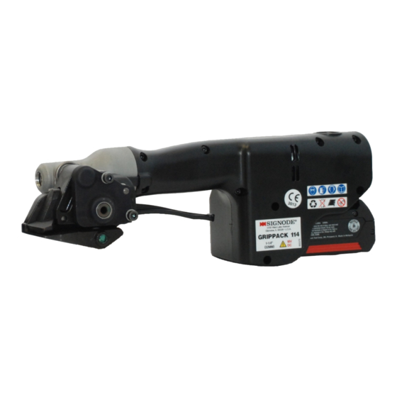
- Page 1 GRIPPACK BATTERY POWERED TENSIONER NOTE: Fully charge battery before first use of tool. SIGNODE ! 3700 WEST LAKE AVENUE ! GLENVIEW, ILLINOIS 60026...
-
Page 2: General Safety Instructions
5. STRAPPING Several types of strap can be used with this tool. Use the correct Signode products for your application. If you need help contact your Signode Representative. 6. CUTTING TENSIONED STRAP Use only cutters designed for cutting strap;... - Page 3 Inspect tool, battery and charger periodically and, if damaged, have repaired by authorized service facility. 12. USE FOR THE INTENDED PURPOSE This tool is designed for bundling round packages with Signode brand steel strapping. POSSIBLE MISUSES The use of any other strapping material may void this tool’s warranty.
- Page 4 Read the operating instructions carefully. This tool must not be used by persons not properly trained in its use. Be certain that you receive proper training from your employer. If you have any questions contact your Signode Representative. EYE INJURY HAZARD Failure to wear safety glasses with side shields can result in severe eye injury or blindness.
-
Page 5: Table Of Contents
PRODUCT IDENTIFICATION Tool, Battery & 220 Volt Charger, Part No. 800467 A two letter date code can be found on every tool. Contact your local Signode representative to assist in identifying the production month and year of the tool. Date codes can also be used to properly STRAP SPECIFICATIONS identify service parts for this tool. -
Page 6: Major Components
MAJOR TOOL COMPONENTS... -
Page 7: Battery Charger
BATTERY INFORMATION & CHARGING Plug charger into your standard power outlet. With no battery pack inserted, the charger's green indicator light will go ON. This indicates the charger is receiving power and the charger is ready for operation. When you insert the battery pack into the charger. The charger's green indicator light will begin to "BLINK". - Page 8 If the red indicator light is "BLINKING", the battery pack cannot accept a charge. Check to make sure the battery pack is inserted to the charger properly. Clean the contacts of the charger or battery pack (e. g. by inserting and removing the battery several times) or replace the battery pack as required.
-
Page 9: Operating Instructions
Wear safety glasses and gloves. Stand to one side of the strap when sealing. Make sure all bystanders are clear before proceeding. SELECTING OPERATING MODE The GripPack is easily changed from Manual Mode to Automatic Mode. When in MODE selection the tool will NOT operate. - Page 10 If you have any questions, contact your local Signode Representative. Strap tension is controlled by setting the control on the rear of the tool. Adjust the tool to give the desired tension level.
- Page 11 Press and hold the start button to reverse the tool. 5. Once the strap has been fully tensioned use a Signode approved tool to seal the joint. Squeeze the gripper lever to open the tool. Place the top strap into the front nose opening and slide the tool forward until it butts against the seal.
- Page 12 Bend the strap end backwards as shown. button to reverse the tool. 5. Once the strap has been fully tensioned use a Signode approved tool to seal the joint. Squeeze the gripper lever to open the tool. Place the top strap into the front nose opening and slide the tool forward until it butts against the seal.
-
Page 13: Parts List & Exploded Views
PARTS LIST - MAIN ASSEMBLIES PART NO. DESCRIPTION Notes: 800442 GEAR HOUSING ASSY 800445 BREAKER FOOT ASSY 800119 PIVOT PIN Ø10 x 55 1. Torque: 22 in-lbs (2.5 Nm) 800415 FOOT SPRING 2. Loctite 401 or equivalent. 423398 FEEDWHEEL 3. Torque: 6 in-lbs (.68 Nm) 423521 SIDEPLATE ASSY 4. - Page 14 PARTS LIST - PLASTIC HOUSING ASSEMBLY (800444) PART NO. DESCRIPTION 800397 PLASTIC HOUSING LEFT Notes: 800398 PLASTIC HOUSING RIGHT 800424 BRASS INSERT M3 1. Torque: 10 in-lbs (1.13 Nm) 800423 BRASS INSERT M4 2. Torque: 6 in-lbs (.68 Nm) 800426 DOWEL PIN 4 x 30 800395 PCB ASSEMBLY...
- Page 15 PARTS LIST - GEAR HOUSING ASSEMBLY (800442) PART NO. DESCRIPTION Notes: 008752 N5000-62 008751 NEEDLE ROLLER BEARING 1. Loctite 609 (Green) or 008756 BEARING equivalent. 800436 RETAINING RING 2. Part side with lettering 024038 BEARING must be installed facing 423533 THRUST WASHER gear housing.
- Page 16 PARTS LIST - GEAR BODY ASSEMBLY (800443) PART NO. DESCRIPTION 800603 GEAR BODY 800453 GEAR RING 800236 SBHCS M4 X5 800454 RING Note 1: Loctite 222 or Equivalent. PARTS LIST - GEARING (800453) PART NO. DESCRIPTION 800256 RING GEAR 800251 IDLER CARRIER ASSEMBLY 800258 IDLER...
- Page 17 PARTS LIST - BREAKER FOOT ASSEMBLY (800445) PART NO. DESCRIPTION 800410 BREAKER FOOT 252262 NOSE PIN 8 X 26 800602 BREAKER NOSE 423524 ROLLER PIN 10 X 50 423517 ROLLER 423546 NOSE SPRING ! Recommended spare parts items: 1, 2, 3, 4, 5 PARTS LIST - MOTOR ASSEMBLY (800447) PART NO.
- Page 18 PARTS LIST - SIDE PLATE ASSEMBLY (800451) PART NO. DESCRIPTION 800411 SIDE PLATE 800451 BUSHING ! Recommended spare parts items PARTS LIST - ELECTRICAL COMPONENTS Individual Part Description 800428 Operation Button 800422 Motor 800425* Switch 800414* Strap Sensor 800395 PC Board 800005 Contact Plate 800427...
-
Page 19: Troubleshooting Guides
TROUBLESHOOTING GUIDES... - Page 20 TROUBLESHOOTING GUIDES...
- Page 21 TROUBLESHOOTING - INDICATOR LIGHTS Charger is plugged in and receiving power. Battery is receiving a Quick Charge. Battery is too hot or cold to receive charge. Charging starts when the battery reaches the proper temperature. Battery cannot accept a charge. Replace battery. LOW BATTERY CHARGE LED flashes 1 second on, one second off, etc.
-
Page 22: Tool Maintenance
If there is any question that joint formation is not as shown or is suspect, it is important that you contact your tool representative immediately. TOOL LUBRICATION Signode tools use a variety of greases and oils, all of which can be ordered through Signode. When ordering indicate tool model, part number and name. THREAD SEALANTS Signode tools are assembled using a variety of thread sealants, all of which can be ordered through Signode service using the appropriate description and part number. -
Page 23: Maintenance Procedures
MAINTENANCE PROCEDURES - CONTROLS DIAGNOSTIC Use the following procedure to diagnose a possible faulty or broken control switch. 2 small pieces of strapping are needed for this procedure. The diagnostics feature is enabled for 30 seconds. If all components have not been verified within 30 seconds repeat steps 1 through 4 and resume. - Page 24 MAINTENANCE PROCEDURES - CYCLE COUNTER Use the following procedure to access the cycle count of the tool. This is the total number of times the tool has been operated and can aid in diagnosing problems or service schedules. 1 small piece of strapping is needed for this procedure. The tool counts from 0 to 999,999.
- Page 25 MAINTENANCE PROCEDURES - FEEDWHEEL CLEARANCE The feedwheel to roller clearance may require readjustment if the feedwheel or roller has been replaced. The freewheel clearance should also be inspected during routine tool maintenance procedures. Adjust the feedwheel clearance as follows: Using a 2.5mm hex wrench turn the adjustment screw which can be accessed through the top of the tool as shown.
- Page 27 3700 West Lake Avenue Glenview, IL 60026 U.S.A. Place of Declaration: U.S.A. Declaration Date: 1 March, 2013 Machine Description: Grippack Machine Type: Battery Powered Hand Tool Provisions with which machinery complies: 2006/42/EC 2006/95/EC 2004/108/EC Harmonized EuroNorms with which machinery complies:...
- Page 28 SIGNODE WARRANTIES AND LIMITATIONS Signode warrants that for a period of sixty (60) days for Signode tools from date of shipment product sold to Purchaser by Signode will be free from defects in material and workmanship under normal use. During said Warranty period, Signode agrees to replace free of charge any Signode manufactured or purchased part or component which is determined to be defective.
Need help?
Do you have a question about the GRIPPACK and is the answer not in the manual?
Questions and answers