Table of Contents
Advertisement
Advertisement
Table of Contents

Related Manuals for weintek CMT Series


Summary of Contents for weintek CMT Series
- Page 1 User Manual V1.0.1...
-
Page 2: Table Of Contents
Table of Contents Chapter1. Overview ............................1 1.1. Specification ............................1 1.2. Dimensions ............................2 1.3. Pin Assignment ........................... 3 1.4. Restoring factory default ........................3 1.5. LED indicator ............................3 1.6. Battery ..............................4 1.7. Power connection ..........................4 1.8. - Page 3 Edit Node ............................27 6.5. Certificates ............................28 6.6. Discovery ............................29 6.7. Advanced ............................30 Chapter7. Installing Weintek Built-in CODESYS .................... 31 Chapter8. Connecting cMT-CTRL01 CODESYS ....................33 8.1. Connecting Through Network ......................33 8.2. Creating CODESYS Project ........................ 33 Chapter9.
-
Page 4: Overview
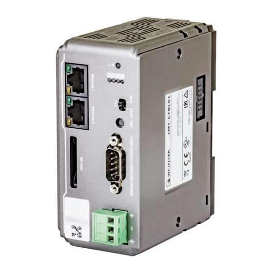
cMT-CTRL01 User Manual Chapter1. Overview 1.1. Specification CODESYS PLC with IIoT Gateway Features CODESYS PLC compliant with IEC61131-3 Fan-less Cooling System Built- in 4GB Flash Memory and RTC SD Card Slot Supports SD/SDHC Cards Rich combination of iR Series Modules Gateway ... -
Page 5: Dimensions
cMT-CTRL01 User Manual 英文版 1.2. Dimensions Top View 50mm [1.97"] 81mm [3.19"] Side View Side View Front View Bottom View RUN/STOP switch LAN 1 Reset Button LAN 2 COM1: RS-232, COM2: RS-485 2W/4W, SD Card Slot COM3: RS-485 2W Power Connector Expansion Connector V1.0.1... -
Page 6: Pin Assignment
cMT-CTRL01 User Manual 1.3. Pin Assignment COM1 [RS232], COM2 [RS-485 2W/4W], COM3 [RS-485 2W], 9 Pin, Male, D-sub COM2 [RS-485] COM1 COM3 PIN# [RS-232] [RS-485] 2W Data+ Data- Data+ Data- 1.4. Restoring factory default Press and hold on the Reset button on the unit for more than a certain period of time when the RUN/Stop toggle switch (CODESYS switch) is in STOP state: Period of time ERR LED... -
Page 7: Battery
For more information on battery replacement and disposal considerations, please refer to the following link: http://www.weintek.com/download/MT8000/eng/FAQ/FAQ_103_Replace_Battery_en.pdf 1.7. Power connection Power: The unit can be powered by DC power only, the voltage range is compatible with most controller DC systems. -
Page 8: Power Consumption
cMT-CTRL01 User Manual Power Connector Specifications: Wire AWG: 24~12 Wiring Conductor Minimum Temperature: 75°C Screw Torque: 4.5 lbf-in (max.) Copper conduct only Note: Connect positive DC line to the '+' terminal and the DC ground to the '-' terminal. 1.8. Power Consumption Type Device Consumption(5V) -
Page 9: Chapter2. Cmt-Ctrl01 System Setting
Connect cMT-CTRL01 via Ethernet cable, and then configure system settings by the following ways. 2.1. Search for cMT-CTRL01’s IP address Launch UtilityManagerEX. On the top-left menu select cMT Series, and then select a function from Reboot, Download, or Upload. cMT-CTRL01 can be found in the IP/HMI Name group box by using the model’s IP address, even if the PC or laptop is not on the same network. -
Page 10: System Setting
cMT-CTRL01 User Manual cMT-CTRL01 system information is shown in the Login page, and the language used can be changed in this page. Icon Description Displays HMI name. Displays system date. Displays system time. Please note that by default, LAN 2 is assigned for Gateway (DHCP). 2.3. -
Page 11: Network
cMT-CTRL01 User Manual Three levels of privileges can be found: [System Setting]: Controls all the settings [Update]: Controls limited items. [History]: Downloads history data (Recipes and Event Logs). 2.3.1. Network Configure Ethernet ports: IP, Mask, Gateway, and DNS. cMT-CTRL01 is equipped with dual Ethernet ports that can be freely assigned as one of the following: One Ethernet port for CODESYS (LAN1, DHCP) and the other one for IIoT Gateway (LAN2 DHCP). -
Page 12: Hmi Name
cMT-CTRL01 User Manual 2.3.3. HMI Name Enter a name to identify the unit. [Identification light]: The LED indicator of the unit will flash three times when this button is clicked, helping user to find the unit. 2.3.4. History This tab offers settings related to historical data. [Clear]: Clears history data. -
Page 13: Email
cMT-CTRL01 User Manual 2.3.5. Email This tab offers settings related to email. [SMTP]: Configure email server and relevant settings. [Contacts]: Set email contacts in this tab. [Update Email Contacts]: Import the email contacts built using Administrator Tools. 2.3.6. Project Management This tab offers settings related to project management. -
Page 14: System Password
cMT-CTRL01 User Manual [Update Project]: Upload the project’s *.cxob file to cMT-CTRL01. [Backup Project]: Backup the project file to this computer. [USB/SD Update]: Use the project file stored in the external device to update the project file on cMT-CTRL01. 2.3.7. System Password Set login password and the password for transferring project file. -
Page 15: Easyaccess 2.0 (Optional)
cMT-CTRL01 User Manual 2.3.9. EasyAccess 2.0 (Optional) This tab shows Hardware Key, EasyAccess 2.0 activate status, and proxy settings. For more information on EasyAccess 2.0, please see EasyAccess 2.0 User Manual. 2.3.10. OPA UA Configure OPC UA settings. Please see “Chapter 6 OPC UA Web Management Interface” in this manual for details. - Page 16 cMT-CTRL01 User Manual V1.0.1...
- Page 17 cMT-CTRL01 User Manual Parameters that can be viewed and modified for a device connected via COM port. Interface Baud rate Data Bits Parity Stop Bits Timeout Parameter 1 Parameter 2 Send ACK Delay Parameters that can be viewed and modified for a device connected via Ethernet. IP Address Port Timeout...
-
Page 18: Chapter3
cMT-CTRL01 User Manual Chapter3. Updating Web Package and OS cMT-CTRL01 Web Package and OS can be updated through Ethernet. Launch Utility ManagerEX, select [Gateway Series] » [Maintenance] » [cMT-Gateway OS Update]. 3.1 Updating Web Package 1. Select an HMI to update OS. 2. - Page 19 cMT-CTRL01 User Manual 2. Select [OS], a Warning message shows, please read this message carefully before you click [OK]. 3. If you click [OK], the cMT-Gateway OS Update window opens again, browse for the source file, and then click [Update]. 4.
- Page 20 cMT-CTRL01 User Manual V1.0.1...
-
Page 21: Chapter4
cMT-CTRL01 User Manual Chapter4. How to create a cMT-CTRL01 project This chapter explains how to create a project when cMT-CTRL01 is used as an OPC UA Server. The basic steps are: 1. Add a driver into Device List in EasyBuilder Pro. 2. -
Page 22: Download Project To Cmt-Ctrl01
cMT-CTRL01 User Manual Step 3. Click [IIoT/Energy] » [OPC UA Server], and select [Enable] check box to enable OPC UA Server. Step 4. Click [Tags] of the device and then click [New Tag] to add tags monitored using OPC UA. When finished, click [OK] to leave. - Page 23 cMT-CTRL01 User Manual [Compile] to compile the project into *.cxob format. When finish compiling, you can download the project to cMT-CTRL01 by two ways. Way 1: Download using EasyBuilder Pro. Click [Project] » [Download(PC->HMI)], and set HMI IP address. The project can be downloaded via Ethernet. Way 2: Download using website.
-
Page 24: Monitoring Opc Ua Client
cMT-CTRL01 User Manual 4.3. Monitoring OPC UA Client After downloading the project file, use OPC UA Client software to connect with cMT-CTRL01 to monitor PLC data. Note: The above is a screenshot of UaExpert. For more information on OPC UA Client software settings, please see OPC UA server manual. - Page 25 cMT-CTRL01 User Manual Step 3. In On-line Simulation, data in PLC tags will also change. V1.0.1...
-
Page 26: Chapter5. Functions Supported By Cmt-Ctrl01
User Manual Chapter5. Functions supported by cMT-CTRL01 OPC UA Server http://www.weintek.com/download/EBPro/Document/UM016009E_OPC_UA_UserManual_en.pdf EasyAccess 2.0 (Optional) http://www.weintek.com/download/EasyAccess20/Manual/eng/EasyAccess2_UserManual_en.pdf Modbus TCP/IP Gateway OPC UA Client MQTT Server / MQTT Subscriber / MQTT Publisher Administrator Tools Time synchronization (NTP) ... -
Page 27: Chapter6
cMT-CTRL01 User Manual Chapter6. OPC UA Web Management Interface 6.1. Introduction cMT-CTRL01 provides a web-based tool for convenient access to OPC UA configurations. Open cMT-CTRL01’s webpage by entering its IP address into the address bar of a web browser. At the entry page, log in with System setting’s password. -
Page 28: Startup / Shut Down
cMT-CTRL01 User Manual Usage of each window tab: Description Configure server settings such as port, name, security, user Server settings authentication……etc. Edit node Manage tags used by OPC UA server. Certificates Manage certificates used by OPC UA server. Discovery Manage list of discovery server. Advanced Advanced options and features. - Page 29 cMT-CTRL01 User Manual General Function Port Access port of the OPC UA server Server name Server name of the OPC UA server Supported security policies. At least one must be selected. Security policy Supported Policy: None, Basic128Rsa15, Basic256, Basic256sha256 Mode: Sign, Sign & Encrypt Automatically Trust all client certificates: by enabling this option, the Option OPC UA server will trust the certificate from any client connection.
-
Page 30: Edit Node
cMT-CTRL01 User Manual After completing settings, click the Save button to save the changes. OPC UA server will shut down momentarily and then restart for the changes to take effect. 6.4. Edit Node In this page, the user can view and manage the tags currently available in the OPC UA server. New nodes and groups can be added, while existing nodes and groups can be edited or deleted. -
Page 31: Certificates
cMT-CTRL01 User Manual Note that all modifications can only be made for existing drivers. It is not possible to change or add other drivers that are not already available. It is also not possible to edit the nodes used by tag PLCs*. -
Page 32: Discovery
cMT-CTRL01 User Manual Page Description Lists of trusted/rejected client certificates on the server. Trusted Clients Supported operation: Trust/Reject, Remove, Import, Export. Lists of trusted/rejected user certificates on the server. Supported Trusted Users operation: Trust/Reject, Remove, Import, Export. Server’s own certificate. Supported operation: Update, Remove. -
Page 33: Advanced
cMT-CTRL01 User Manual After completing settings, click the Save button to save the changes. OPC UA server will shut down momentarily and then restart for the changes to take effect. 6.7. Advanced Additional settings can be configured in the Advanced tab. The user can set the trace logging level and specific startup behavior of the OPC UA server. -
Page 34: Chapter7. Installing Weintek Built-In Codesys
User Manual Chapter7. Installing Weintek Built-in CODESYS Installing Weintek Built-in CODESYS allows users to easily create a cMT+CODESYS project in CODESYS software. Please find the Package file we prepared and follow these steps for quick installation. First, get a copy of CODESYS Package file. - Page 35 cMT-CTRL01 User Manual The installed component will be shown in the installation summary. V1.0.1...
-
Page 36: Chapter8
cMT-CTRL01 User Manual Chapter8. Connecting cMT-CTRL01 CODESYS 8.1. Connecting Through Network Connect cMT-CTRL01’s LAN 1 port with a router or PC. Open internet browser (IE, Chrome, Firefox, Safari), enter cMT-CTRL01’s IP address (e.g. 192.168.100.1), and then configure cMT-CTRL01 settings. Open CODESYS page to see the IP address. By default DHCP is used for cMT-CTRL01 CODESYS IP. - Page 37 User Manual Select Weintek Built-in CODESYS. CODESYS software provides 6 languages that can be selected in [PLC_PRG in:] drop-down list as shown below. Structure Text (ST) is used as an example in this manual. Double-click on Device (Weintek Built-in CODESYS) to open the settings window.
- Page 38 cMT-CTRL01 User Manual The project will connect the selected device. IP address of the device can be entered in the field shown below. V1.0.1...
-
Page 39: Chapter9. Creating Easybuilder Project
cMT-CTRL01 User Manual Chapter9. Creating EasyBuilder Project *Please use EasyBuilder Pro v6.04.01 or later versions. 9.1. Creating Tags Create several tags in PLC_PRG tab and make tag “test” accumulate automatically. 9.2. Exporting Tags Right-click on Application in Devices tree and then select [Add Object] » [Symbol Configuration], use defaults. -
Page 40: Configuring Easybuilder
User Manual 9.3. Configuring EasyBuilder Create a project and select Weintek Built-in CODESYS in the device list. Open Tag Manager and click , and then click [Import Tag] to import the *.xml file built in preceding steps. The CODESYS tags can now be found in Tag Manager. -
Page 41: Chapter10
cMT-CTRL01 User Manual Chapter10. Connecting cMT-CTRL01 CODESYS to iR Series Modules Right-click on [iBus (iBus)] and then select [Add Device]. Select an iR module and then click [Add Device]. The added device can be found under iBus. You may add more modules with this window is left opened. - Page 42 cMT-CTRL01 User Manual Analog modules, other modules, and their settings. iBus has two addresses in BYTE type that show low voltage and I/O error. Open PLC_PRG in Devices tree and configure variables as shown below. In Devices tree double click on an iR module name to open object settings window. In iROption I/O Mapping tab, select a variable for the object.
- Page 43 cMT-CTRL01 User Manual When finished, click [Online] » [Login] to download the project to CODESYS. V1.0.1...
-
Page 44: Chapter11
cMT-CTRL01 User Manual Chapter11. Connecting cMT-CTRL01 to iR-ETN 11.1. Connecting cMT-CTRL01 to iR-ETN Right-click on Device (cMT-CTRL01) and then select [Add Device]. Select [Ethernet Adapter] » [Ethernet] and then click [Add Device]. Ethernet (Ethernet) can be found in Devices tree. Double-click on Ethernet with the current window opened in Devices tree or right-click on Ethernet and then select [Add Device]. - Page 45 cMT-CTRL01 User Manual select [Add Device]. Double click on Ethernet in the Devices tree, enter CODESYS’s IP address in General tab, and then select [Change Operating System Settings]. When [Use operating System Settings] is selected, settings on cMT-CTRL01 will be used without being changed. When CODESYS is already connected, go to General tab and click the […] button near Interface field and select eth0.
- Page 46 cMT-CTRL01 User Manual Open [Modbus Slave Channel] tab and create Modbus Variable. Open PLC_PRG in Devices tree, create tag and set Bool as data type. Write a command as shown below. V1.0.1...
-
Page 47: Connecting Codesys And Modbus Tcp/Ip Gateway
cMT-CTRL01 User Manual Open Modbus_TCP_Slave in Devices tree and then go to [Modbus_TCPSlave I/O Mapping] tab to set up iR-ETN’s IP address and Unit ID. When finished, click [Online] » [Login] to download the project to CODESYS. 11.2. Connecting CODESYS and Modbus TCP/IP Gateway cMT-CTRL01 supports Modbus TCP/IP Gateway which allows CODESYS to access Modbus TCP/IP Gateway using Modbus TCP Slave, in order to control the devices connected to Modbus TCP/IP Gateway. - Page 48 cMT-CTRL01 User Manual objects to read. When setting Modbus Slave Channel, Cycle Time can be configured to adjust the frequency at which data is written to the registers. For more information on Modbus Gateway, please see EasyBuilder Pro User Manual Chapter 37 MODBUS TCP IP Gateway.
-
Page 49: Chapter12
User Manual Chapter12. Removing Weintek Built-in CODESYS Click [Tools] » [Packages Manager]. Find Weintek Built-in CODESYS and then click [Uninstall]. Click [Next] when seeing the window below. Removing the program. Click [Finish]. V1.0.1... - Page 50 cMT-CTRL01 User Manual V1.0.1...
-
Page 51: Chapter13
cMT-CTRL01 User Manual Chapter13. Frequently Asked Questions 13.1. Questions Related to CODESYS When the indicator of CODESYS Gateway lights up in red, how can I connect to the device? A: When CODESYS Gateway is not properly started or installed, its indicator will light up in red. Please try the following 3 methods to solve this situation. -
Page 52: Questions Related To Downloading Cmt Codesys File
How to update CODESYS firmware? There are 2 ways to update CODESYS firmware. Launch Utility Manager and select cMT Series » Maintenance » CODESYS Firmware Update. Browse for the firmware file and click [Update]. Enter cMT HMI’s IP address in the website browser and find [CODESYS] » [CODESYS update] tab. - Page 53 cMT-CTRL01 User Manual Enter cMT HMI’s IP address in the website browser and find [CODESYS] » [Project update] tab. Select the files generated in the previous step and click [Update]. V1.0.1...
Need help?
Do you have a question about the CMT Series and is the answer not in the manual?
Questions and answers