Advertisement
Quick Links
Installation Instructions
Phone, Navigation Systems
SUBJECT
BMW Universal Bluetooth
MODEL
E39 - Sedan as of 3/02
E39 - Sport Wagon as of 9/02
"Never use any electronic device or make any inputs while driving that may distract you from driving
safely.
Pay attention to traffic laws and road conditions\situations. Safe vehicle operation is the driver's
responsibility. Always wear your safety belt."
INSTALLATION TIME
The average installation time for this kit is approximately 1 hour.
These instructions were developed especially for BMW vehicles and are not to be compared to any
existing instructions for vehicles other than BMW. No methods other than those specified in this
document are to be used to install the BMW Universal Bluetooth
Please initial and route to the following for information before filing
X
Service Manager
X
Service Advisor
X
Service Advisor
X
Shop Foreman
FIX IT RIGHT THE FIRST TIME, ON TIME, EVERY TIME
2003 BMW of North America, LLC
TM
Hands-Free-Kit
X
Warranty
Parts Mgr.
Body Shop
PDI Dept.
B84 02 03
TM
Hands-Free Kit.
X
Service Technicians - Initial Below
Page 1 of
June 2003
Product
Development
by: KRS
Advertisement

Subscribe to Our Youtube Channel
Related Manuals for BMW B84 02 03


Summary of Contents for BMW B84 02 03
- Page 1 The average installation time for this kit is approximately 1 hour. These instructions were developed especially for BMW vehicles and are not to be compared to any existing instructions for vehicles other than BMW. No methods other than those specified in this document are to be used to install the BMW Universal Bluetooth Hands-Free Kit.
-
Page 2: Parts Information
PARTS INFORMATION Description BMW Part Number ULF Control Module 84 21 6 934 552 Voice Input System Jumper Plug 84 11 0 018 038 ULF Control Module Mounting Bracket 84 13 6 924 547 (Sedan with Navigation produced 3/02 – 8/02) - Page 3 2. To remove the armrest, first remove the oddment tray (2) from the rear of the console using a plastic pry tool (1) to release the taps on the tray, then pull the tray out. 3. Slide the ventilation grill (1) down 4.
- Page 4 7. Apply the adhesion promoter (1) to an area in the center console (2). 8. Remove the protective strip from one side of the double-sided tape and place the double-sided tape (1) onto the base of the antenna. 9. Remove the protective strip from the double- sided tape and install the Bluetooth antenna with the tape (1),P/N 84 50 8 928 461 into the...
- Page 5 11. Insert the eject box (1), P/N 84 21 6 933 415 into the armrest (2) by feeding the wires/connectors from the eject box (3) through the opening in the armrest assembly. 12. Connect the black female FAKRA connector (2) to the male connector and connect the black 18-pin ELO connector (1) to the 18-pin ELO connector X4545.
- Page 6 C. ULF Control Module Installation 1. Remove/ peel off the Bluetooth Passkey sticker (2) from the label on the ULF Control Module (1). 2. Place the Bluetooth Passkey sticker removed from the ULF Control Module onto the ULF Passkey Reference Card, P/N 84 11 0 302 638. 3.
- Page 7 3. Install three M5 Clip Nuts (2), P/N 61 13 1 372 033, on the ULF Control Module-mounting bracket. Note: Mounting bracket P/N 84 13 6 924 547 should be installed in all E39 Sedans as of 9/02 production. 4. Install the ULF Control Module (1), P/N 84 21 6 934 552.
- Page 8 E39 Sedan - Produced 3/02 through 8/02 without Navigation 1. For vehicles produced 3/02 through 8/02 without navigation installed, a ULF Control Module mounting bracket, P/N 84 13 6 924 546, will need to be installed. 2. Install three M5 Clip Nuts (K), P/N 61 13 1 372 033, on the ULF Control Module-mounting bracket.
- Page 9 7. Connect the Black 54 pin connector (2) and white FAKRA connector (1) to the Control Module (F). E39 Sport Wagon (as of 9/02) 1. Remove the floor panel located directly behind the rear seats to gain access to the ULF Control Module mounting bracket (1) and connectors (2).
- Page 10 3. Secure the ULF Control Module (F) to the mounting bracket (G) using three M5 hex bolts (I), P/N 07 11 9 902 932. 4. Locate the telephone system connector bundle, and connect the white female FAKRA connector (1) and black 54-pin connector (3) to the ULF Control Module (G).
-
Page 11: Function Test
Follow the on screen requests to activate the coding procedure. F. Function test Upon completion of the recoding, verify that the BMW Universal BluetoothTM Hands-Free System is working correctly by going through the following action steps. After completing each step ensure that... -
Page 12: Troubleshooting
G. Troubleshooting: Situation Correction No audio output through vehicle speakers Check SES module jumper plug Radio does not mute after placing a call Check connections at rear of radio for Tel On and Tel Mute signal. Verify that connectors and pins are properly seated. - Page 13 H. Pairing Procedure: The pairing procedure that must be initiated through the phone will differ corresponding to the different menu configurations of the various Bluetooth mobile phones on the market. The user’s manual of the phone should always be referenced for specific steps on how to activate the Bluetooth feature and to pair/link devices.
- Page 14 10. Enter password (= ULF passkey) located on ULF Control Module in the rear of the vehicle or on the Passkey Reference Card. • Mobile Phone display shows ‘BMW …… Pairing’ • Mobile Phone display shows ‘Pairing Successful’ • Board Monitor display shows ‘Pairing succeeded’ for 3 seconds 11.
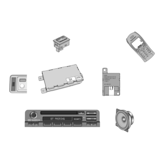
- Page 15 COMPONENT LOCATION: SPORT WAGON SEDAN A - Eject Box E - Microphone D - Bluetooth Antenna F - ULF Control Module...
- Page 16 ULF Wiring Schematic E39 with Boardmonitor Unloader relay terminal R Light from terminal 30 Switch input X10018 Bluetooth Antenna X4545 X9988 Eject Box X4545 X01041 X9987 X01185 Control Module X01185 X10390 Jumper Plug to other modules from K3 from terminal 30 unloader relay X10390 X2759...
- Page 17 ULF Wiring Schematic E39 with Multi Information Display Unloader relay terminal R Light from terminal 30 Switch input X10018 Bluetooth Antenna X4545 X9988 Eject Box X4545 X01041 X9987 X01185 Control Module X01185 X10390 Jumper Plug to other modules from K3 from terminal 30 unloader relay X10390...
Need help?
Do you have a question about the B84 02 03 and is the answer not in the manual?
Questions and answers