Table of Contents
Advertisement
Quick Links
Quick Start
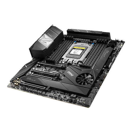
Thank you for purchasing the MSI®
Creator TRX40
motherboard. This Quick Start
section provides demonstration diagrams about how to install your computer. Some
of the installations also provide video demonstrations. Please link to the URL to watch
it with the web browser on your phone or tablet. You may have even link to the URL by
scanning the QR code.
Preparing Tools and Components
3rd Gen AMD Ryzen™
Threadripper™ Desktop
Processor
CPU Fan
Chassis
DDR4 Memory
Power Supply Unit
Graphics Card
Thermal Paste
SATA Hard Disk Drive
SATA DVD Drive
A Package of Screws
Phillips Screwdriver
1
Quick Start
Advertisement
Table of Contents

Related Manuals for MSI Creator TRX40


Summary of Contents for MSI Creator TRX40
-
Page 1: Quick Start
Quick Start Thank you for purchasing the MSI® Creator TRX40 motherboard. This Quick Start section provides demonstration diagrams about how to install your computer. Some of the installations also provide video demonstrations. Please link to the URL to watch it with the web browser on your phone or tablet. You may have even link to the URL by scanning the QR code. -
Page 2: Safety Information
Safety Information ∙ The components included in this package are prone to damage from electrostatic discharge (ESD). Please adhere to the following instructions to ensure successful computer assembly. ∙ Ensure that all components are securely connected. Loose connections may cause the computer to not recognize a component or fail to start. -
Page 3: Installing A Processor
Installing a Processor ⚽ https://youtu.be/yk4EpVUU03E Quick Start... -
Page 4: Installing Ddr4 Memory
Installing DDR4 memory ⚽ http://youtu.be/T03aDrJPyQs 1 DIMM 3rd Gen AMD Ryzen™ 2 DIMMs Threadripper™ Desktop 4 DIMMs Processors 8 DIMMs Quick Start... -
Page 5: Connecting The Front Panel Header
Connecting the Front Panel Header ⚽ http://youtu.be/DPELIdVNZUI Power LED Power Switch JFP1 Reserved HDD LED Reset Switch HDD LED + Power LED + HDD LED - Power LED - Reset Switch Power Switch JFP1 Reset Switch Power Switch Reserved No Pin HDD LED - HDD LED HDD LED +... -
Page 6: Installing The Motherboard
Installing the Motherboard Quick Start... -
Page 7: Connecting The Power Connectors
Connecting the Power Connectors ⚽ http://youtu.be/gkDYyR_83I4 ATX_PWR1 CPU_PWR1 CPU_PWR2 Quick Start... -
Page 8: Installing Sata Drives
Installing SATA Drives http://youtu.be/RZsMpqxythc Quick Start... -
Page 9: Installing A Graphics Card
Installing a Graphics Card http://youtu.be/mG0GZpr9w_A Quick Start... -
Page 10: Connecting Peripheral Devices
Connecting Peripheral Devices Quick Start... -
Page 11: Power On
Power On Quick Start... -
Page 12: Table Of Contents
Contents Quick Start ......................1 Preparing Tools and Components................1 Safety Information ....................2 Installing a Processor .................... 3 Installing DDR4 memory ..................4 Connecting the Front Panel Header ..............5 Installing the Motherboard ..................6 Connecting the Power Connectors ................ 7 Installing SATA Drives .................... - Page 13 POWER1, RESET1: Power Button, Reset Button ..........45 JTPM1: TPM Module Connector ................46 JBAT1: Clear CMOS (Reset BIOS) Jumper ............46 JCI1: Chassis Intrusion Connector ............... 47 JRGB1: RGB LED connector ................. 48 JRAINBOW1~2: Addressable RGB LED connectors ..........49 JCORSAIR1: CORSAIR Connector ................
- Page 14 Microphone Tab ....................80 Sound Tracker Tab ....................81 Settings Tab ......................81 AMD RAID Configuration ..................82 Enabling RAIDXpert2 Configuration Utility ............82 Initializing Disks ....................83 Creating Arrays..................... 84 Deleting Arrays ..................... 85 Installing RAID Driver ................... 86 Troubleshooting ....................
-
Page 15: Specifications
∙ Supports non-ECC UDIMM memory ∙ Supports ECC UDIMM memory ∙ Supports un-buffered memory * For the latest information about memory, please visit http://www.msi.com ** Please refer the DIMM Slots section for more details. 4x PCIe 4.0 x16 slots (support x16/x8/x16/x8 mode) Expansion Slot ∙... - Page 16 Continued from previous page Intel® Wi-Fi 6 AX200 ∙ The Wireless module is pre-install in the M2_4 (Key-E) slot WiFi & Bluetooth ∙ Supports 802.11 a/b/g/n/ac/ax, MU-MINO Rx, 2.4GHz- 5GHz (160MHz) up to 2.4Gbps ∙ Supports Bluetooth® 5 ∙ AMD® TRX40 Chipset ▪...
- Page 17 Continued from previous page ∙ 1x 24-pin ATX main power connector ∙ 2x 8-pin ATX 12V power connectors ∙ 6x SATA 6Gb/s connectors ∙ 3x M.2 slots (M-Key) ∙ 1x USB 3.2 Gen2 Type-C port ∙ 2x USB 3.2 Gen1 connectors (supports additional 4 USB 3.2 Gen1 ports) ∙...
- Page 18 ∙ Drivers ∙ CREATOR CENTER ∙ Nahimic Audio ∙ CPU-Z MSI GAMING Software ∙ MSI App Player (BlueStacks) ∙ Open Broadcaster Software (OBS) ∙ Google Chrome™, Google Toolbar, Google Drive ∙ Norton™ Internet Security Solution ∙ Creator Optimization ∙ Creator Hotkey ∙...
- Page 19 Continued from previous page ∙ Audio ▪ Audio Boost 4 ▪ Nahimic 3 ▪ Voice Boost ∙ Network ▪ 10G SUPER LAN ▪ LAN Manager ▪ Dual LAN ▪ Intel WiFi ∙ Storage ▪ Lightning Gen4 M.2 ∙ Cooling ▪ FROZR Heastink Design ▪...
-
Page 20: Jcorsair1 Connector Specification
Continued from previous page ∙ Performance ▪ Lightning Gen 4 PCI-E Slot ▪ Multi GPU – SLI Technology ▪ Multi GPU – CrossFire Technology ▪ DDR4 Boost ▪ Core Boost ▪ OC Engine(Clock gen) ▪ USB with type A+C ▪ AMD Turbo USB 3.2 Gen 2 ▪... -
Page 21: Package Contents
Package contents Please check the contents of your motherboard package. It should contain: Motherboard Creator TRX40 User manual Documentation Quick installation guide Application USB drive with drivers & utilities SATA 6G cable LED JRGB Y cable Cables LED JCORSAIR cable... -
Page 22: Block Diagram
Block Diagram 4 channel DDR4 memory Processor 2x M.2 PCIe Bus 4x USB 3.2 Gen2 Realtek ALC1220 PCIe x8 Audio jacks Realtek ALC4050H Audio header 1x Intel® Wi-Fi 6 AX200 6x SATA 6Gb/s TRX40 8x USB 3.2 Gen1 1x Intel® I211AT 4x USB 2.0 1x USB 3.2 Gen2 Type C 1x Aquantia®... -
Page 23: Rear I/O Panel
Rear I/O Panel USB 3.2 Gen2 Wi-Fi Antenna connectors Gigabit 10Gigabit Audio Ports Clear CMOS button Flash BIOS Port USB 3.2 Gen1 Flash BIOS Button Optical S/PDIF-Out USB 3.2 Gen2 USB 3.2 Gen2x2 Type-C USB 3.2 Gen2 ∙ Clear CMOS button - Power off your computer. Press and hold the Clear CMOS button for about 5-10 seconds to reset BIOS to default values. -
Page 24: Realtek Audio Console
Realtek Audio Console After Realtek Audio Console is installed. You can use it to change sound settings to get better sound experience. Application Enhancement Device Selection Main Volume Connector Settings Jack Status ∙ Device Selection - allows you to select a audio output source to change the related options. - Page 25 Audio jacks to headphone and microphone diagram Audio jacks to stereo speakers diagram AUDIO INPUT Audio jacks to 7.1-channel speakers diagram AUDIO INPUT Rear Front Side Center/ Subwoofer Rear I/O Panel...
-
Page 26: Installing Antennas
Installing Antennas 1. Combine the antenna with the base. 2. Screw two antenna cables tight to the WiFi antenna connectors as shown. 3. Place the antenna as high as possible. Rear I/O Panel... -
Page 27: Overview Of Components
Overview of Components DIMMC1 DIMMA1 DIMMC2 DIMMA2 DIMMD1 DIMMB1 CPU Socket DIMMD2 DIMMB2 PUMP_FAN1 CPU_FAN1 CPU_PWR1 CPU_PWR2 T_SEN3 SYS_FAN1 EXS_FAN3 JCORSAIR1 ATX_PWR1 M2_3 JUSB3 PCI_E1 JUSB4 JBLK_D1 JBLK_U1 PCI_E2 JUSB5 M2_1 PCI_E3 M2_2 SATA▼1▲2 JOC_RT1 JOC_FS1 SATA▼3▲4 PCI_E4 JCI1 SATA▼5▲6 JBAT1 JRAINBOW1 SYS_FAN4... - Page 28 Component Contents Port Name Port Type Page CPU_FAN1, PUMP_FAN1, Fan Connectors SYS_FAN1~4, EXS_FAN1~3, CPU_PWR1~2, ATX_PWR1 Power Connectors CPU Socket Socket sTRX4 DIMM Slots Memory Slots JAUD1 Front Audio Connector JBAT1 Clear CMOS (Reset BIOS) Jumper JBLK_D1, JBLK_U1 Base Clock Down & Up Header JCI1 Chassis Intrusion Connector JCORSAIR1...
-
Page 29: Cpu Socket
CPU Socket Distance from the center of the CPU to the nearest DIMM slot. 44.61 mm 44.61 mm ⚽ Video Demonstration Watch the video to learn how to unbox and install AMD Ryzen Threadripper CPU. https://youtu.be/yk4EpVUU03E Please use the Torx screwdriver come with the AMD CPU and follow the steps below to install the CPU. - Page 30 3. Remove the protective pin cap, and then close and buckle the frame rail. Protective pin cap 4. Close the load plate, and then turn the load plate screws clockwise a little with the AMD Torx screwdriver in the sequence 1→2→3→1→2→3 until they are snug. AMD Torx screwdriver 5.
- Page 31 Always unplug the power cord from the power outlet before installing or removing ∙ the CPU. Please retain the protective caps after installing the processor. MSI will deal with ∙ Return Merchandise Authorization (RMA) requests if only the motherboard comes with the protective caps on the CPU socket.
-
Page 32: Dimm Slots
DIMM Slots D2 D1 C2 C1 A1 A2 B1 B2 Memory module installation recommendation CPU Socket 1 DIMM 3rd Gen AMD Ryzen™ 2 DIMMs Threadripper™ Desktop 4 DIMMs Processors 8 DIMMs DIMMB2 DIMMB2 DIMMD2 Overview of Components... - Page 33 It is recommended to use a more efficient memory cooling system for full DIMMs installation or overclocking. The stability and compatibility of installed memory module depend on installed CPU ∙ and devices when overclocking. Please refer www.msi.com for more information on compatible memory. ∙ Overview of Components...
-
Page 34: Pci_E1~4: Pcie Expansion Slots
PCI_E1~4: PCIe Expansion Slots PCI_E1: PCIe 4.0 x16 PCI_E2: PCIe 4.0 x8 PCI_E3: PCIe 4.0 x16 PCI_E4: PCIe 4.0 x8 Multiple graphics cards installation recommendation PCI_E1* PCI_E1* PCI_E3 PCI_E1* PCI_E3 PCI_E4 * To prevent monitor blank during the system POST. If you have multiple graphics cards installed, as marked above, connect your monitor to the graphics card located on the first PCIe x16 slot. - Page 35 ⚠ Important ∙ If you install a large and heavy graphics card, you need to use a tool such as MSI Gaming Series Graphics Card Bolster to support its weight to prevent deformation of the slot. For a single PCIe x16 expansion card installation with optimum performance, using ∙...
-
Page 36: Cpu_Pwr1~2, Atx_Pwr1: Power Connectors
CPU_PWR1~2, ATX_PWR1: Power Connectors These connectors allow you to connect an ATX power supply. CPU_PWR1/ CPU_PWR2 Ground +12V Ground +12V Ground +12V Ground +12V +3.3V +3.3V +3.3V -12V Ground Ground PS-ON# Ground Ground Ground ATX_PWR1 Ground Ground PWR OK 5VSB +12V +12V +3.3V... -
Page 37: M2_1~3: M.2 Slots (Key M)
M2_1~3: M.2 Slots (Key M) ⚽ M2_3 (PCH) Video Demonstration Watch the video to learn how to Install M.2 module. M2_1 (CPU) http://youtu.be/JCTFABytrYA M2_2 (CPU) Installing M.2 module 1. Loosen the screws of M.2 SHIELD FROZR. 2. Remove the M.2 SHIELD FROZR and remove the protective films from the thermal pads. - Page 38 8.5H screw Standoff Thermal pad-1 Protecting films Thermal pad-2 M.2 Plate ⚠ Important Pictures shown are for illustration purpose only and may differ from the actual plates and thermal pads. 5. Move the position of the standoffs according to your M.2 SSDs length if need. 6.
-
Page 39: Installing M.2 Xpander-Aero Gen4
Installing M.2 XPANDER-AERO GEN4 To install the M.2 XPANDER-AERO GEN4 card, please follows the steps below. 1. Remove the heatsink by loosening four screws on the back of the M.2 XPANDER- AERO GEN4 card. 2. Loosen M.2 screw from M.2 standoff. 3. - Page 40 9. Insert the M.2 XPANDER-AERO GEN4 card into the PCI_E3 slot. 10. Use two screws to secure the M.2 XPANDER-AERO GEN4 card. PCI_E3 11. Connect the PCIE_PWR1 to the power supply. 12. Connect the case’s HDD LED cable to the JCASE connector. 13.
-
Page 41: Sata1~6: Sata 6Gb/S Connectors
SATA1~6: SATA 6Gb/s Connectors These connectors are SATA 6Gb/s interface ports. Each connector can connect to one SATA device. SATA2 SATA1 SATA4 SATA3 SATA6 SATA5 ⚠ Important ∙ Please do not fold the SATA cable at a 90-degree angle. Data loss may result during transmission otherwise. -
Page 42: Jusb1~2: Usb 2.0 Connectors
In order to recharge your iPad,iPhone and iPod through USB ports, please install ∙ MSI CREATOR CENTER utility. JUSB3: USB 3.2 Gen2 Type-C Connector This connector allows you to connect the USB 3.2 Gen2 Type-C connector on the front panel. -
Page 43: Jusb4~5: Usb 3.2 Gen1 Connectors
JUSB4~5: USB 3.2 Gen1 Connectors These connectors allow you to connect USB 3.2 Gen1 ports on the front panel. Power USB2.0+ USB3_RX_DN USB2.0- USB3_RX_DP Ground Ground USB3_TX_C_DP USB3_TX_C_DN USB3_TX_C_DN USB3_TX_C_DP Ground Ground USB3_RX_DP USB2.0- USB3_RX_DN USB2.0+ Power ⚠ No Pin Important Note that the Power and Ground pins must be connected correctly to avoid possible damage. -
Page 44: Cpu_Fan1, Pump_Fan1, Sys_Fan1~4, Exs_Fan1~3,: Fan Connectors
CPU_FAN1, PUMP_FAN1, SYS_FAN1~4, EXS_FAN1~3,: Fan Connectors Fan connectors can be classified as PWM (Pulse Width Modulation) Mode or DC Mode. PWM Mode fan connectors provide constant 12V output and adjust fan speed with speed control signal. DC Mode fan connectors control fan speed by changing voltage. This motherboard can automatically detect PWM and DC mode. -
Page 45: T_Sen1~3: Thermal Sensor Connectors
T_SEN1~3: Thermal Sensor Connectors These connectors allow you to connect the thermistor cable and use it to monitor the temperature of the detection point. Thermistor cable Sense JBLK_D1, JBLK_U1: Base Clock Down & Up Header These connectors allow you to connect the buttons separately and then press the button to turn the CPU base clock down or up. -
Page 46: Jtpm1: Tpm Module Connector
JTPM1: TPM Module Connector This connector is for TPM (Trusted Platform Module). Please refer to the TPM security platform manual for more details and usages. LPC Clock 3V Standby power LPC Reset 3.3V Power LPC address & data pin0 Serial IRQ LPC address &... -
Page 47: Jci1: Chassis Intrusion Connector
JCI1: Chassis Intrusion Connector This connector allows you to connect the chassis intrusion switch cable. Normal Trigger the chassis intrusion event (default) Using chassis intrusion detector 1. Connect the JCI1 connector to the chassis intrusion switch/ sensor on the chassis. 2. -
Page 48: Jrgb1: Rgb Led Connector
(12V/G/R/B) with the maximum power rating of 3A (12V). ∙ Always turn off the power supply and unplug the power cord from the power outlet before installing or removing the RGB LED strip. Please use MSI’s software to control the extended LED strip. ∙ Overview of Components... -
Page 49: Jrainbow1~2: Addressable Rgb Led Connectors
(5V). In the case of 20% brightness, the connector supports up to 200 LEDs. Always turn off the power supply and unplug the power cord from the power outlet ∙ before installing or removing the RGB LED strip. ∙ Please use MSI’s software to control the extended LED strip. Overview of Components... -
Page 50: Jcorsair1: Corsair Connector
The JCORSAIR1 connector allows you to connect the CORSAIR Individually Addressable RGB LED strips 5V or CORSAIR RGB LED fans with the CORSAIR fan hub. Once all items are connected properly, you can control the CORSAIR RGB LED strips and fans with MSI's software. JCORSAIR1 Data... -
Page 51: Joc_Rt1: Oc Retry Button
JOC_RT1: OC Retry Button This connector allows you to connect a button. When you press and hold the button, the system will keep retrying OC items until it boot up successfully. JOC_FS1: OC Force Enter BIOS Button This connector allows you to connect a button. When you press the button, the system will be forced into BIOS without showing the OC_FAIL message. -
Page 52: Onboard Leds
Onboard LEDs EZ Debug LED These LEDs indicate the debug status of the motherboard. CPU - indicates CPU is not detected or fail. DRAM - indicates DRAM is not detected or fail. VGA - indicates GPU is not detected or fail. BOOT - indicates the booting device is not detected or fail. -
Page 53: Debug Code Led
Debug Code LED The Debug Code LED displays progress and error codes during and after POST. Refer to the Debug Code LED table for details. Debug Code LED Hexadecimal Character Table Hexadecimal Debug Code 0 1 2 3 4 5 6 7 8 9 A B C D E F LED display Boot Phases Security (SEC) –... - Page 54 SEC Error Codes 0C - 0D Reserved for future AMI SEC error codes Microcode not found Microcode not loaded PEI Progress Codes PEI Core is started Pre-memory CPU initialization is started 12 - 14 Pre-memory CPU initialization (CPU module specific) Pre-memory System Agent initialization is started 16 - 18 Pre-Memory System Agent initialization (System Agent module specific)
- Page 55 64 - 67 CPU DXE initialization (CPU module specific) PCI host bridge initialization System Agent DXE initialization is started System Agent DXE SMM initialization is started 6B - 6F System Agent DXE initialization (System Agent module specific) PCH DXE initialization is started PCH DXE SMM initialization is started PCH devices initialization 73 - 77...
- Page 56 Ready To Boot event Legacy Boot event Exit Boot Services event Runtime Set Virtual Address MAP Begin Runtime Set Virtual Address MAP End Legacy Option ROM Initialization System Reset USB hot plug PCI bus hot plug Clean-up of NVRAM Configuration Reset (reset of NVRAM settings) B8 - BF Reserved for future AMI codes DXE Error Codes...
-
Page 57: Acpi States Codes
S3 OS Wake Error EC - EF Reserved for future AMI error codes Recovery Progress Codes Recovery condition triggered by firmware (Auto recovery) Recovery condition triggered by user (Forced recovery) Recovery process started Recovery firmware image is found Recovery firmware image is loaded F5 - F7 Reserved for future AMI progress codes Recovery Error Codes... -
Page 58: Installing Os, Drivers & Utilities
Installing OS, Drivers & Utilities Please download and update the latest utilities and drivers at www.msi.com Installing Windows® 10 1. Power on the computer. 2. Insert the Windows® 10 installation disc/USB into your computer. 3. Press the Restart button on the computer case. -
Page 59: Bios Setup
BIOS Setup The default settings offer the optimal performance for system stability in normal conditions. You should always keep the default settings to avoid possible system damage or failure booting unless you are familiar with BIOS. ⚠ Important ∙ BIOS items are continuously update for better system performance. Therefore, the description may be slightly different from the latest BIOS and should be for reference only. -
Page 60: Resetting Bios
Updating BIOS Updating BIOS with M-FLASH Before updating: Please download the latest BIOS file that matches your motherboard model from MSI website. And then save the BIOS file into the USB flash drive. Updating BIOS: 1. Insert the USB flash drive that contains the update file into the USB port. - Page 61 1. Please download the latest BIOS file that matches your motherboard model from the MSI® website. 2. Rename the BIOS file to MSI.ROM, and save it to the root of your USB flash drive (FAT32 format). 3. Connect the power supply to CPU_PWR1 and ATX_PWR1. (No need to install CPU and memory.)
-
Page 62: Ez Mode
EZ Mode At EZ mode, it provides the basic system information and allows you to configure the basic setting. To configure the advanced BIOS settings, please enter the Advanced Mode by pressing the Setup Mode switch or F7 function key. A-XMP switch Setup Mode switch Screenshot... - Page 63 ∙ Boot device priority bar - you can move the device icons to change the boot priority. The boot priority from high to low is left to right. ∙ Information display - click on the CPU, Memory, Storage, Fan Info and Help buttons on left side to display related information.
-
Page 64: Advanced Mode
Advanced Mode Press Setup Mode switch or F7 function key can switch between EZ Mode and Advanced Mode in BIOS setup. Setup Mode switch Screenshot A-XMP switch Language System information Boot device OC GENIE 4 priority bar switch BIOS menu BIOS menu selection selection... -
Page 65: Settings
SETTINGS System Status ▶ System Date Sets the system date. Use tab key to switch between date elements. The format is <day> <month> <date> <year>. <day> Day of the week, from Sun to Sat, determined by BIOS. Read-only. <month> The month from Jan. through Dec. <date>... - Page 66 Sets the PCI Express protocol for matching different installed devices. This item will appear when Above 4G memory/Crypto Currency mining is enabled. ▶ PCIe SlotX Lanes Configuration PCIe lanes configuration is for MSI M.2 XPANDER-AERO GEN4 card. The options in this item will vary with the installed processor. ▶ ACPI Settings Sets ACPI parameters of onboard power LED behaviors.
- Page 67 ▶ LAN Option ROM [Disabled] Enables or disables the legacy network Boot Option ROM for detailed settings. This item will appear when Onboard LAN Controller is enabled. [Enabled] Enables the onboard LAN Boot ROM. [Disabled] Disables the onboard LAN Boot ROM. ▶...
- Page 68 ▶ Legacy USB Support [Enabled] Sets Legacy USB function support. [Auto] The system will automatically detect if any USB device is connected and enable the legacy USB support. [Enabled] Enable the USB support under legacy mode. [Disabled] The USB devices will be unavailable under legacy mode. ▶...
- Page 69 ▶ Wake Up Event By [BIOS] Selects the wake up event by BIOS or operating system. [BIOS] Activates the following items, set wake up events of these items. [OS] The wake up events will be defined by OS. ▶ Resume By RTC Alarm [Disabled] Disables or enables the system wake up by RTC Alarm.
-
Page 70: Boot
Boot Sets the sequence of system boot devices. ▶ Full Screen Logo Display [Enabled] Enables or disables to show the full screen logo while system POST. [Enabled] Shows the logo in full screen. [Disabled] Shows the POST messages. ▶ Bootup NumLock State [On] Select the keyboard NumLock state upon bootup. -
Page 71: Security
Security ▶ Administrator Password Sets administrator password for system security. User has full rights to change the BIOS items with administrator password. After setting the administrator password, the state of this item will show Installed. ▶ User Password Sets User Password for system security. User has limited rights to change the BIOS items with user password. -
Page 72: Save & Exit
▶ Chassis Intrusion [Disabled] Enables or disables recording messages while the chassis is opened. This function is ready for the chassis equips a chassis intrusion switch. [Enabled] Once the chassis is opened, the system will record and issue a warning message. [Reset] Clear the warning message. - Page 73 ⚠ Important ∙ Overclocking your PC manually is only recommended for advanced users. ∙ Overclocking is not guaranteed, and if done improperly, it could void your warranty or severely damage your hardware. If you are unfamiliar with overclocking, we advise you to use OC GENIE 4 function for ∙...
- Page 74 ▶ Memory Try It ! [Disabled] It can improve memory compatibility or performance by choosing optimized memory preset. ▶ Memory Failure Retry [Enabled] Allows system attempt reboot. If filed in the end, system will boot up with default settings safely. [Disabled] System would not boot up due OC fail, it requires clear CMOS to restore system default settings.
- Page 75 ▶ CPU Features Press Enter to enter the sub-menu. ▶ Simultaneous Multi-Threading [Enabled] (optional) Enables/ disables the AMD Simultaneous Multi-Threading. This item appears when the installed CPU supports this technology. ▶ Global C-state Control [Enabled] (optional) Enables/ disables IO based C-state generation and DF C-states. ▶...
-
Page 76: M-Flash
M-FLASH provides the way to update BIOS with a USB flash drive. Please down-load the latest BIOS file that matches your motherboard model from MSI website, save the BIOS file into your USB flash drive. And then follow the steps below to update BIOS. -
Page 77: Oc Profile
OC PROFILE ▶ Overclocking Profile 1/ 2/ 3/ 4/ 5/ 6 Overclocking Profile 1/ 2/ 3/ 4/ 5/ 6 management. Press <Enter> to enter the sub- menu. ▶ Set Name for Overclocking Profile 1/ 2/ 3/ 4/ 5/ 6 Name the current overclocking profile. ▶... -
Page 78: Hardware Monitor
HARDWARE MONITOR Speed Fan Manage Setting Buttons Temperature Voltage ▶ Speed/ Temperature/ Voltage Instantly display fan speed, temperature, and voltage for CPU, memory, and system environments. ▶ Fan Manage ▪ PWM - allows you to select the PWM mode for fan operation. ▪... -
Page 79: Nahimic 3
Sound Tracker. Installation and Update Nahimic 3 is included in the audio driver. If you need to install it or update it, please use the MSI USB drive with your motherboard or download the driver from MSI’s official website. Audio Tab From this tab, you can access all of Nahimic 3’s audio effects, audio profiles and... -
Page 80: Microphone Tab
▪ Voices - it boosts (or removes) the speech in movies, video games and incoming communication from -12 to +12 dB. ▪ Bass - increases (or decreases) the energy in low frequencies from -12 to +12 ▪ Treble - increases (or decreases) the energy in high frequencies from -12 to +12 ∙... -
Page 81: Sound Tracker Tab
Sound Tracker Tab The Sound Tracker is an FPS oriented feature that provides a visual indication localizing the sources of the sounds while in a game. These are represented by dynamic segments pointing the direction of the sounds: the more opaque they are, the stronger the sounds are. -
Page 82: Amd Raid Configuration
AMD RAID Configuration The following are the RAID levels supported by RAIDXpert2. RAID 0 (Striping) breaks the data into blocks which are written to separate hard drives. Spreading the hard drive I/O load across independent channels greatly improves I/O performance. RAID 1 (Mirroring) provides data redundancy by mirroring data between the hard drives and provides enhanced read performance. -
Page 83: Initializing Disks
Initializing Disks New disks and legacy disks must be initialized before they can be used to create an AMD-RAID array. Initialization writes AMD-RAID configuration information (metadata) to a disk. ⚠ Important ∙ If a disk is part of an AMD-RAID array, the disk cannot be selected for initialization. To initial the disk anyway, delete the AMD-RAID array. -
Page 84: Creating Arrays
Creating Arrays Arrays can be created after the disks are initialized. ⚠ Important For redundant arrays, the Create process is not started until after the operating ∙ system and AMD-RAID OS drivers have been installed and the system has booted to the operating system. -
Page 85: Deleting Arrays
Deleting Arrays ⚠ Important Deleting an array permanently destroys all data that is on the array. This action ∙ cannot be undone and it is very unlikely that the data can be recovered. ∙ Do not delete the first array listed in the Arrays section, if it is the AMD-RAID bootable array. -
Page 86: Installing Raid Driver
1. During the operating system installation, after selecting the location to install Windows click on Load driver button to install a third party RAID driver. 2. When prompted, insert the MSI USB drive and then click Browse. 3. Navigate to \\Storage\AMD\ the directory containing AMD RAID drivers, then click 4. -
Page 87: Troubleshooting
Troubleshooting Lost BIOS password Before sending the motherboard for RMA repair, try to go over troubleshooting ∙ Clear the CMOS, but that will cause guide first to see if your got similar you to lose all customized settings in the symptoms as mentioned below. - Page 88 European Harmonized Standards. disposing of their end-of-life products. The point of contact for regulatory matters is MSI, • Visit the MSI website and locate a nearby distributor MSI-NL Eindhoven 5706 5692 ER Son. for further recycling information. B급 기기 (가정용 방송통신기자재) •...
- Page 89 MSI la Unión Europea al final de su periodo de vida. Usted will comply with the product take back requirements...
- Page 90 Products designed to be operated del suo ciclo di vita. MSI si adeguerà a tale Direttiva at closer proximities, such as tablet computers, ritirando tutti i prodotti marchiati MSI che sono stati comply with applicable EU requirements in typical venduti all’interno dell’Unione Europea alla fine del...
- Page 91 Copyright © 2019 All rights reserved. contact your place of purchase or local distributor. The MSI logo used is a registered trademark of Alternatively, please try the following help resources Micro-Star Int’l Co., Ltd. All other marks and names for further guidance.
Need help?
Do you have a question about the Creator TRX40 and is the answer not in the manual?
Questions and answers