Table of Contents
Advertisement
Quick Links
About SunFounder
SunFounder is a technology company focused on Raspberry Pi and Arduino open source
community development. Committed to the promotion of open source culture, we strive to
bring the fun of electronics making to people all around the world and enable everyone to
be a maker.
Our products include learning kits, development boards, robots, sensor modules and
development tools. In addition to high quality products, SunFounder also offers video
tutorials to help you make your own project. If you have interest in open source or making
something cool, welcome to join us!
About This Kit
This cute learning kit focuses on the popular open source platform Arduino. You can learn
the knowledge of the Arduino servo and ultrasonic ranging module by applying this kit.
In this book, we will show you how to build the biped robot via description, illustrations of
physical components, in both hardware and software respects. You may visit our website
www.sunfounder.com
-> Get Tutorials
and watch related videos under VIDEO.
Free Support
If you have any TECHNICAL questions, add a topic under
website and we'll reply as soon as possible.
For NON-TECH questions like order and shipment issues, please
service@sunfounder.com. You're also welcomed to share your projects on FORUM.
Preface
to download the related code and view the user manual on
LEARN
FORUM
section on our
send an email to
Advertisement
Table of Contents

Subscribe to Our Youtube Channel
Related Manuals for SunFounder Sloth Learning Kit


Summary of Contents for SunFounder Sloth Learning Kit
- Page 1 Preface About SunFounder SunFounder is a technology company focused on Raspberry Pi and Arduino open source community development. Committed to the promotion of open source culture, we strive to bring the fun of electronics making to people all around the world and enable everyone to be a maker.
-
Page 2: Table Of Contents
Content Components............................1 i. Structural Plate..........................1 ii. Mechanical Fasteners........................1 iii. Electrical Components....................... 2 iv. Battery(Not Included)......................3 Introduction............................4 Getting Started..........................4 Arduino..............................5 Install Arduino IDE..........................5 Install the Driver..........................6 Add Libraries..........................6 Test for Servos and Ultrasonic Module..................7 i. Servo Test............................7 ii. - Page 3 Summary............................32 Copyright Notice..........................33...
-
Page 4: Components
Components Structural Plate Mechanical Fasteners Parts Name Qty. -
Page 5: Electrical Components
M1.5*5 Self-tapping Screw M1.4*8 Screw M2*8 Screw M3*5 Screw M3*8 Countersunk Screw M1.4 Nut M2 Nut M3 Self-locking Nut M3*8 Bi-pass Copper Standoff M3*25 Bi-pass Copper Standoff iii. Electrical Components Parts Name Qty. SF006C Servo Ultrasonic Module SunFounder Nano Board... -
Page 6: Battery(Not Included
Please check the above list and structural plate drawings against the product you received to check for missing components. If the above two situations occur, please take pictures of all the components you have received and inform us of the missing parts,and send E-mail to service@sunfounder.com... -
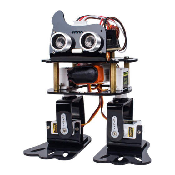
Page 7: Introduction
Arduino servo and ultrasonic ranging module by applying this kit. It is a new mobile robot called Sloth developed by SunFounder. Each leg has 2 joints driven by servo. One 9V chargeable lithium batteries are to supply the bot when the SunFounder Nano is used as the control board, compatible with the Arduino Nano. -
Page 8: Arduino
Arduino senses the environment by receiving inputs from many sensors, and affects its surroundings by controlling lights, motors, and other actuators. In this kit, SunFounder Nano board is used. Install Arduino IDE The code in this kit is written based on Arduino, so you need to install the IDE first. Skip it if you have done this. -
Page 9: Install The Driver
Find the one that suits your operation system and click to download. There are two versions of Arduino for Windows: Installer or ZIP file. You're recommended to download the former. Just download the package, and run the executable file to start installation. It will download the driver needed to run Arduino IDE. -
Page 10: Test For Servos And Ultrasonic Module
Then you will see “Library added to your libraries”, indicating the library has been included successfully. Test for Servos and Ultrasonic Module Before assembling, you need to test the servos and the ultrasonic module according to the following steps. Servo Test 1. - Page 11 If the servo does not work properly, we believe that the servo has been damaged. Software Test Insert SunFounder Nano board into the Servo Control Board. Note: The USB port should be at the same side with blue power supply terminal.
- Page 12 And connect the battery cable to the expansion board. Connect four servos to pin 9 to pin 12 of the expansion board. Note: The yellow, red, and brown wires connect to Signal, VCC, and GND on the expansion board, respectively. Select the right board to Nano board in IDE.
- Page 13 Then select the right port and upload the sketch. After waiting for a few seconds, the download process is successful. The following window will prompt “Done uploading”.
-
Page 14: Ultrasonic Test
Press the power button on the servo control board. You will see the rocker arm rotates within 0-180 degrees, indicating the servo can work. Then press the power button again to turn it off. Keep the Test_robot.ino file open, and ii. Ultrasionic Test still needs to use this file in the next step. - Page 15 Go to line 10 and 11, you can see that TRIGGER_PIN is defined as 5 and ECHO_PIN is defined as 4. And connect the pin TRIG to pin 4 of the servo control board. ECHO to pin 3, VCC to V and GND to G.
-
Page 16: Assembly
Upload the program to the Nano board, open the serial monitor. Then press the power button on the servo control board. Set the baud rate as 115200, hold the ultrasonic module and make the two ultrasonic “eyes” facing an obstacle, move the robot back and forth, and observe the data shown on serial monitor. -
Page 17: Electrical Module Assembly
Use a M3*5 screw to secure the M3*8 two-way hexagonal copper post on No. 1 board. ii. Electrical Module Assembly Use a M3*5mm screw to mount the previously installed circuit board on No. 1 board. Use M3*5 screws to fix M3*25 Bi-pass Copper Standoff under the No. 1 board. -
Page 18: Servo Assembly
iii. Servo Assembly Use M2*8 screws and M2 nuts to mount the servo on the corresponding position on the No. 2 board. (Note the direction of the servo installation) Secure the No. 1 and No. 2 boards with M3*5 screws. Note that the side of the servo shaft should be mounted on the side of the USB port. - Page 19 Use two M1.5*5 self-tapping screws to fix the 2-arm rocker arm to the No. 4 board and use the same method to install another No. 4 board.
- Page 20 Secure one of the round holes on the 4th and 5th boards with M3*8 Countersunk screws Use the same method to secure the other round hole on the 4th and 5th boards, as shown Use two M1.5*5 self-tapping screws to secure the 1-arm rocker arm on the No.4 board.
- Page 21 nd M3 self-locking nuts. in the following figure: Install another No.4 board in the same way.
- Page 22 Turn the No. 6 board with the countersunk side down and secure the No. 6 board to the ① module (right leg) described above with the M3*8 countersunk screw and the M3 selflocking nut. ② module (left leg). The same method can be used to secure the No.7 and the...
-
Page 23: Servo Install Test
iv. Servo INSTALL Test Connect the upper-right servo to port 9, the yellow cable to the signal pin, red to the positive pole and brown to the negative pole. Then connect the lower-right servo, the upper-left one and the lower-left servo to pin 10, 11 and 12 respectively in the same way. Connect the Nano board and the computer with a USB cable. -
Page 24: Foot Assembly
v. Foot Assembly Assemble the No.4 board on the left leg and the No.3 board on the cover together with the upper-left servo through the servo's matching screws (the smallest screws in the packaged with servo). Try to keep the edges of the 4th board and the servo parallel to each other. They need to be reinstalled if not parallel to each other. - Page 25 The lower-right servo (pin 10) is installed in the same way. Insert the 1-arm rocker arm into the two servos and secure them with the matching screws of the servo. The effect chart is as follows:...
-
Page 26: Battery Assembly
vi. Battery Assembly Attach one side of velcro tape to the bottom of the No. 1 board and the other side to the battery. Insert the battery into the battery cable and plug the other end into the expansion board. Lastly, paste the battery on the No. -
Page 27: Servo Calibration Test
vii. Servo CALIBRATION Test Open the program and go to Line 39, the INSTALL and the CALIBRATION. disable activate Select the correct board and port, then upload the sketch. If the robot is not set right, change the angle and upload the code until it is. Tips for calibration: If the right leg is toe out, you need to decrease the upper-right servo’s angle;... - Page 28 Here we take this robot as an example. After uploading the code, press thepower button on the servo control board, pick up the robot and you will see the slight change of the robot legs and feet: Observe the robot above we can know: ① right leg is toe out, ② left leg is toe out, ③ right foot’s sole faces outward, ④...
- Page 29 Change 100 degrees to 90 (array_cal[1]: is the lower-right servo’s rotation angle); Increase the lower-left servo’s angle Change 95 degrees to 100 (array_cal[3]: is the lower-left servo’s rotation angle); i.e.: In line 15, change code to array_cal[4] = {90, 90, 120, 100}; Then click Upload. The edge of upper-left plate and upper plate are parallel with each other, but upper-right is not parallel to the upper one, the deviation angles of lower-left and lower-right servos are decreased.
-
Page 30: Ultrasonic Connecting
Observe the four servos to make sure they are in proper angle, then the servo calibration is completed. You can do fine tuning with value changing of “1” each time, if there is a little deviation. Since the servo angles on legs and feet differ, the final calibrated angles (array_cal[4]) will be different too. -
Page 31: Servo Run Test
Connect pin TRIG of the ultrasonic to pin 4 of the board, ECHO to pin 3, VCC to VCC and GND to GND. ix. Servo RUN Test Go to Line 39 again, the CALIBRATION line. disable Activate the operating programe “run” and burn the program to the board. -
Page 32: Wire Arrangement
After burning successfully, unplug the USB cable and press the power button on the servo control board. You will see the robot moving forward. When encountering an obstacle, it will make a turn and then go forward again. x. Wire Arrangement Twine the servo wire and 4-Pin anti-reverse cable on the No. -
Page 33: Q&A
So far the robot has been assembled successfully, it’s easy if you follow our steps closely. Hope you enjoy the fun of the bot, thanks for watching. Q&A Q1: How can we know the servo is damaged? A1: In Servo Test step, if the servo rocker arm shake, get stuck or can not rotate smoothly, with an abnormal sound, we can judge it as a damaged one. - Page 34 b) If rebooting happens in moving backward actions, you can decrease “vel_Back” or/ and increase “delay_Backward”. For instance, decrease “vel_Back” to 8, and increase “delay_Backward” to 1500. You can adjust to a proper value as you want. Then click Upload. Sloth walks too slowly when it moves forward.
- Page 35 change the value of vel and delay_Forward in line12 and 13 to as shown: vel = 50, delay_Forward = 500 Then click Upload. Note: If you adjust the robot to a high walking speed, it may fall down and break. Thus it’s better to do some protection for the Sloth.
- Page 36 All contents including but not limited to texts, images, and code in this manual are owned by the SunFounder Company. You should only use it for personal study, investigation, enjoyment, or other non-commercial or nonprofit purposes, under the related regulations and copyrights laws, without infringing the legal rights of the author and relevant right holders.
Need help?
Do you have a question about the Sloth Learning Kit and is the answer not in the manual?
Questions and answers