Table of Contents
Advertisement
Quick Links
TOSHIBA Wireless LAN Kit
B-EP700-WLAN-QM-R Installation Manual
Thank you for purchasing TOSHIBA wireless LAN kit, B-EP700-WLAN-QM-R.
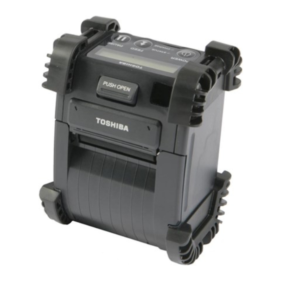
The B-EP700-WLAN-QM-R is an optional wireless LAN interface module for the B-EP2DL/EP4DL Series.
The pictures used in this document are those of the B-EP4DL, but the installation procedure is common with the
B-EP2DL unless otherwise noted.
1. Follow all manual instructions. Failure to do so could create safety hazards such as fire or electrocution.
• Manual instructions must be followed when installing option kits or adding cables to avoid system
failures and to insure proper performance and operation.
• Failure to follow manual instructions or any unauthorized modifications, substitution or change to this
product will void the limited product warranty.
2. Turn the power off and remove the battery before installing the wireless LAN module.
3. Be careful not to pinch your fingers or hands with the covers.
1. PACKING LIST
The following parts are supplied with the kit. Make sure you have all items shown below.
Wireless LAN Module (1 pc.)
Power
Cable
Shield
Sheet
Installation Manual
(1 copy)
Note:
MAC address is printed on the wireless LAN module, as the following picture shows. Each wireless LAN
module has a unique MAC address. Although the MAC address can be checked by performing a parameter
print in the system mode, write down and keep it just in case that a parameter print cannot be performed or in
case of repair.
MAC
Address
Ground
Wire
Standard Label (1pc.)
WARNING!
FPC Cable
For B-EP2DL Series (1pc.)
Connected to
Wireless LAN module
For B-EP4DL Series (1 pc.)
Connected to
Wireless LAN module
1/8
EO2-38062
Connected to
Main PCB
Ferrite Core
Connected to
Main PCB
Ferrite Core
Advertisement
Table of Contents

Related Manuals for Toshiba B-EP700-WLAN-QM-R


Summary of Contents for Toshiba B-EP700-WLAN-QM-R
-
Page 1: Packing List
Thank you for purchasing TOSHIBA wireless LAN kit, B-EP700-WLAN-QM-R. The B-EP700-WLAN-QM-R is an optional wireless LAN interface module for the B-EP2DL/EP4DL Series. The pictures used in this document are those of the B-EP4DL, but the installation procedure is common with the B-EP2DL unless otherwise noted. -
Page 2: Installation Procedure
2. INSTALLATION PROCEDURE Step 1. Turn off the printer. Step 2. Slide the battery lever in the direction of the arrow, and remove the battery pack from the printer. Step 3. Remove the four tapping screws (T-3x10) from the bottom cover. T-3x10 Tapping Screw Battery Lever Battery Pack... - Page 3 Step 6. Remove the right side cover and the front cover in the direction of the arrow, respectively. Right Side Cover Front Cover Step 7. Connect the FPC cable to the wireless LAN module in the correct orientation. Two FPC cables are supplied with the wireless LAN kit. One is designed for the B-EP2DL series, and the other is for the B-EP4DL series.
- Page 4 Step 9. Connect the FPC cable to CN301 on the Main PC board and power cable to CN302, respectively. Make sure that the FPC cable is connected in the correct orientation. B-EP4DL B-EP2DL Main PC Board CN301 Power Cable Ferrite Core Ferrite Core Main PC Board CN301...
- Page 5 2. Push the SDIO card of the wireless LAN module in the direction of the arrow to make sure it is firmly connected. Connector SDIO Card Wireless LAN module Step11. Close the front cover. Front Cover NOTES: 1. Make sure that the pins on the both sides of the front cover are fit in position, as shown in the pictures below.
- Page 6 Step12. Mount the left side cover to the printer while fitting the tabs on the left side cover into the slots of the printer enclosure. Place the cables avoiding the protrusions on the left side cover. Especially, be carefulof the protrusion E on the cover for the B-EP2DL series. B-EP4DL Series: Fit the tabs A to D into the slot A’...
- Page 7 B-EP2DL Series: Fit the tabs A to C into the slot A’ to C’. Tab C Tab B Tab A C’ B’ A’ NOTE: It is easy to mount the right side cover if you fit the tabs from the LCD side in order, then secure the bottom side. Be careful not to catch the cable by the cover while reassembling.
- Page 8 For Europe for wireless LAN Hereby, TOSHIBA TEC CORPORATION, declares that the SD-Link11g is in compliance with the essential requirements and other relevant provisions of Directive 1999/5/EC. This equipment uses a radio frequency band that has not been harmonized throughout all EU and EFTA countries, and can be used in EU and EFTA countries.
Need help?
Do you have a question about the B-EP700-WLAN-QM-R and is the answer not in the manual?
Questions and answers