Table of Contents
Advertisement
Advertisement
Table of Contents

Related Manuals for OTT Parsivel


Summary of Contents for OTT Parsivel
- Page 1 Operating instructions Present Weather Sensor Parsivel...
- Page 2 We reserve the right to make technical changes!
-
Page 3: Table Of Contents
6.4 Installing the Parsivel 7 Connecting the Parsivel to a data logger 7.1 Connecting the Parsivel to the LogoSens Station Manager via RS-485 interface 7.2 Connecting the Parsivel to a Data logger via the SDI-12 Interface 7.3 Connecting the Parsivel to a Data Logger with Impulse/Status Input 8 Connecting the Parsivel to a PC 8.1 Connecting the Parsivel to Interface Converter RS-485/RS-232 (Accessories) - Page 4 Appendix A: CS Command Set Appendix B: Classification of precipitation types B.1 Class limits Appendix C: Characterization of precipitation type by precipitation codes C.1 Precipitation code according to SYNOP C.2 Precipitation code according to the NWS and METAR/SPECI w’w’, Table 4678 Declaration of Conformity...
-
Page 5: Scope Of Delivery
1 Scope of Delivery – 1 Parsivel measurement head is an optical sensor with 30 mm wide and Parsivel 180 mm long light strip in the tunnel housing – 1 Installation set with 1 screwed terminal strip 7 slots 7 wire end sleeves... -
Page 6: Parsivel Factory Settings
Measurement interval: 30 s The parameters can be set using Parsivel software ASDO or using a terminal soft- ware package. Information on the setting of these parameters is available in Appendix A, “CS Command Set” or in the operating instructions “Parsivel Soft-... -
Page 7: Safety Instructions
Use of other parts can void liability for any conse- quences arising therefrom! The Parsivel contains an embedded class 2 laser device and is a class 1/1M laser product which complies with IEC/EN 60825-1 A2:2001 (EU) / 21CFR 1040.10 and 1040.11 (USA) with the exception of laser notice LN50. -
Page 8: Introduction
Parsivel issues one data telegram every 30 seconds. 5.1 Functional principle The theory behind Parsivel is a laser sensor that produces a horizontal strip of light. The emitter and the receiver are integrated into a single protective housing. Fig. 1: Functional principle of the Parsivel. -
Page 9: Connection Options For The Parsivel
5.2 Connection Options for the Parsivel The Parsivel can be connected to various devices as shown in the illustration below. Refer to the respective chapters in this regard. Parsivel... -
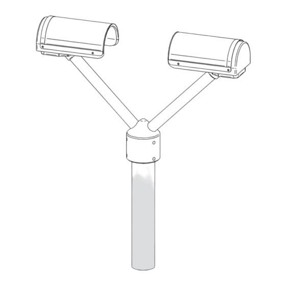
Page 10: Installing The Parsivel
Prerequisites The Parsivel is mounted on a pipe. The pipe must have the following specifications: Pipe diameter 50 … 62 mm Pipe consists of an electrically conducting material and is grounded The concrete foundation of the pipe must have minimum dimensions of 35 x 35 x 80 cm (L x W x H). -
Page 11: Wiring The Parsivel
2.5 mm Hex key supplied. Run the connecting cables from below through the cable gland (see Fig. 7) of the Parsivel and then through the interior of the Parsivel to the opened sensor head. Connect the cables to the 7-slot screw terminal provided (installation set) accor- ding to the configuration of the Parsivel as described in Figures 2 through 4. - Page 12 Plug the screwed terminal strip onto the sensor head as shown in Figure 5. Fig. 5: Plug the screw terminal strip onto the Parsivel sensor head. Re-fasten the bottom cover of the sensor head using the two Allen screws. Tighten the screwed cable connection.
-
Page 13: Grounding The Parsivel
6.3 Grounding the Parsivel To ground the Parsivel, you will need the following parts from the installation set provided: 1 hex key 4 mm 1 M 8 X 25 grub screw 2 lock washers 1 cable lug 1 flat washer... -
Page 14: Installing The Parsivel
Proceed as follows to install the Parsivel: Slide the attached Parsivel downward onto the pipe. Orient the Parsivel such that the laser beam is perpendicular to the local main wind direction. Evenly tighten the 6 M 8 x 16 grub screws, or M 8 x 25 depending on the dia- meter of the pipe stand, using the 4 mm hex key provided (installation set) so that the sensor head is horizontal as much as possible. -
Page 15: Connecting The Parsivel To A Data Logger
The measured values determined by the Parsivel can be queried by the LogoSens station manager and stored. Connect the Parsivel via the RS-485 interface to the LogoSens as shown in figure 8. Fig. 8: Connecting the Parsivel to the LogoSens via the RS-485 interface. - Page 16 Fig. 9: LogoSens Configuration Example when connecting to an RS-485 interface.
-
Page 17: Connecting The Parsivel To A Data Logger Via The Sdi-12 Interface
Parsivel. The measurement time must be ≥1 min in this case in order for the Parsivel to collect sufficient data during winter operation as well to allow for the precise assignment of precipitation type. - Page 18 Configuring the LogoSens Station Manager for SDI-12 communication In order to call up and store data from the Parsivel using the LogoSens, a configu- ration must be created in the LogoSens. Figure 12 shows an example LogoSens configuration for communication via the SDI-12 interface. See operating instruc- tions of “LogoSens Station Manager”...
- Page 19 Fig. 12: LogoSens Configuration Example when connecting to an SDI-12 interface.
- Page 20 You have the option of reading out the measurement data from Parsivel in parallel via an SDI-12 data logger and via the Parsivel software ASDO on a PC (see the operating instructions to Parsivel’s application software ASDO). The SDI-12 data logger specifies the time base for this.
-
Page 21: Connecting The Parsivel To A Data Logger With Impulse/Status Input
7.3 Connecting the Parsivel to a Data Logger with Impulse/Status Input To be able to utilize the impulse and status output of the Parsivel, it is necessary for the 2-wire connection to be activated. The Parsivel is already configured at the factory for 2-wire connection. - Page 22 Status Input With status input, it is possible to differentiate between solid and liquid precipit- ation. For the status output of the Parsivel, the following values apply: Validity period: equal to the sample interval Status voltage: Liquid precipitation = 5 V...
-
Page 23: Connecting The Parsivel To A Pc
Connect the RS-485 interface of the Parsivel to the interface adapter used (see chapter 8.1, 8.2 or 8.3). Connect the interface adapter to the PC. Start the Parsivel Software ASDO or a terminal programm on the PC (such as „Hyperterminal“). Configure and operate Parsivel with the Parsivel software ASDO (see also manual „Parsivel software ASDO“) or alternatively with a terminal software... - Page 24 Connect the interface converter to a PC (RS-232 null modem cable; socket/socket). Connect the power cables of the Parsivel to the power source (see Chapter 9 “Connecting the Power Supply (Accessories) to the Parsivel” Provide power to the interface converter.
-
Page 25: Connecting The Parsivel To The Adam-4520 Converter Rs-485/Rs-232 (Accessories)
S S w w i i t t c c h h 2 2 1 1 0 0 115,2 Kbps 2-wire communication Parsivel is configured at the factory for 2-wire communication. Connect the Parsi- vel as follows: Fig. 18: Connecting the Parsivel to ADAM-4520 converter RS-485/RS-232 in 2-wire communication. -
Page 26: Connecting The Parsivel To Interface Converter Rs-485/Usb (Accessories)
20 m of cable length Interface converter RS-485/USB Parsivel 4-wire communication Connect the Parsivel as follows to the 6-pin terminal of the interface converter for 4-wire communication: Fig. 20: Connecting the Parsivel to an RS-485/USB interface converter in 4-wire communication. -
Page 27: Connecting The Parsivel To Any Rs-485 Interface Converter
Parsivel connection to the PC terminal strip Proceed as follows to connect the Parsivel via the Service Tool to a PC: Install the driver software of the interface converter as described in the original manual of the interface converter. Set the jumper inside the interface converter as shown in fig. 22: Fig. - Page 28 Parsivel as shown in fig. 20.
-
Page 29: Connecting The Parsivel To A Power Supply (Accessory)
Information on the cable necessary for this can be found in Chapter 6.1 “Cable Selection“. Connect the power supply IP 20 or IP 67 to the Parsivel as shown in Figures 23 and 24. Fig. 23: Connecting Power Supply IP 20 to the Parsivel. -
Page 30: Heating The Parsivel Sensor Heads
Note that the sensor head heaters are deactivated at the factory! Activate the sen- sor heaters when using the Parsivel at temperatures below 4 °C! We recommend a power supply of 24V DC and a maximum heating current of 2 A to provide for... -
Page 31: Operating Parsivel With A Terminal Software
® scope of delivery. In order to operate Parsivel using Hyper Terminal, proceed as follows: Connect the Parsivel to your PC as described in chapter 8 “Connecting Parsivel to the PC“. Start Hyper Terminal. After starting Hyper Terminal, the window “Connection Description“ opens. -
Page 32: Measured Value Numbers
11.2 Measured value numbers The measurements and status values are output from the Parsivel in the form of a telegram. To this end, each value that can be output was assigned a measurement number. In addition, the number of digits that the value in the telegram can con- tain, the form in which this value is output and in what units is precisely defined. -
Page 33: Defining The Formatting String
%90; Output data field no. 90 with “;” as a separator Other signs can be used as well as a separator. 11.4 OTT telegram The following telegram configuration has been preset at the factory: %13;%01;%02;%03;%07;%08;%12;%10;%11;%18;/r/n According to this configuration, the measured values are displayed as in the fol- lowing example: 200248;000.000;0000.00;00;-9.999;9999;025;15759;00000;0;... -
Page 34: Updating Parsivel Firmware
Connect your PC to the Parsivel via the corresponding interface converter as described in Chapter 8. Load the newest update of the Parsivel firmware onto your computer from the OTT homepage. Start a terminal software program on your PC and make the corresponding settings as described in Chapter 11.1 “Setting up Communication between Par-... - Page 35 Fig. 28: “Xmodem file send for Parsivel” window The data transfer runs and the window closes automatically after the data transfer has finished. After the window has closed, input the command RUN <CR> to start Parsivel. The firmware was successfully updated.
-
Page 36: Maintenance
2 = Laser protective glass is dirty, partially covered. No further usable measure- ments are possible 3 = Laser damaged It is a good idea to clean the laser optics beginning at status 1. OTT Messtechnik recommends that the laser’s protective glass be cleaned at least semiannually, regardless of the messages. -
Page 37: Cleaning The Splash Protector
The splash protector bends easily! Clean the splash protector on a flat surface! A splash protector is attached to each sensor head of the Parsivel. The splash protector has many small holes that break up incident raindrops so that no secon- dary spectra are detected in the laser beam due to splashing. -
Page 38: Functional Disruptions And Remedies
(see Chapt. 6 and 7). If this does not work, start any terminal software program on your PC (e.g. Hyper Terminal) and try to make a connection to Parsivel (see Chapt. 11 “Operating Parsivel using Terminal Software“). Parsivel should send a status message of “ok“... -
Page 39: Technical Data
2-wire RS 422 1,200 … 57,600 Baud, half-duplex, 4-wire SDI-12 Parsivel has an output relay for simple sta- tus information (rain or snow) and/or impulse output for precipitation in 0.1 mm increments with max. 2 Hz impulse rate Electromagnetic tolerance... -
Page 40: Appendix A: Cs Command Set
If the value “0“ is entered for the sample interval, the Polling mode is active. CS/P<CR> Activating polling mode Parsivel issues a data telegram no later than 500 ms after receiving the command. This command deactivates the interval-controlled telegram. CS/R<CR>... - Page 41 0 … 9 Standard: CS/T/12:00:00<CR> Adjust time of day The time of day of the Parsivel is set to the time of day of the PC. CS/D/01.01.2000<CR> Adjust date The date of the Parsivel is set to the calendar of the PC.
- Page 42 CS/?<CR> This command outputs the command list. CS/H/M/<parameter><CR> This command adjusts the operating mode of the heating system. Value range: 0 … 3 Standard: Description: 0 = Off 1 = Automatic 2 = I 3 = I CS/H/X/<parameter><CR> Adjust I This command sets the maximum current through the heating system.
-
Page 43: Appendix B: Classification Of Precipitation Types
17.000 2.000 19.000 2.000 21.500 3.000 24.500 3.000 Note: Class 1 and Class 2 are limits and are not evaluated at the current time in mea- surements using the Parsivel since they are outside the measurement range of the device. - Page 44 Classification according to speed Class Number Class average in m/s Class spread in m/s 0.050 0.100 0.150 0.100 0.250 0.100 0.350 0.100 0.450 0.100 0.550 0.100 0.650 0.100 0.750 0.100 0.850 0.100 0.950 0.100 1.100 0.200 1.300 0.200 1.500 0.200 1.700 0.200 1.900...
-
Page 45: Appendix C: Characterization Of Precipitation Type By Precipitation Codes
Characterization of precipitation type by precipitation codes From the classification of precipitation particles, Parsivel calculates the rain rate. The type of precipitation is based on the number of particles within the measure- ment range, and the precipitation code is determined from the precipitation inten- sity R (in mm/h of an equivalent amount of water). -
Page 46: Precipitation Code According To The Nws And Metar/Speci W'w', Table 4678
C.2 Precipitation code according to the NWS and METAR/SPECI w’w’, Table 4678 The definitions of the precipitation codes below are listed according to the following tables: METAR/SPECI w’w’ Table 4678 Drizzle Intensity Rain rate [mm/h] Tab. 4678 light ≤0.2 moderate 0.2 …0.5 strong ≥... - Page 48 OTT MESSTECHNIK GmbH & Co. KG Ludwigstrasse 16 ⋅ 87437 Kempten Germany Phone +49 (0)8 31 56 17- 0 +49 (0)8 31 56 17- 2 09 Document number info@ott-hydrometry.com 70.200.005.B.E 07-0806 www.ott-hydrometry.com...
Need help?
Do you have a question about the Parsivel and is the answer not in the manual?
Questions and answers