Table of Contents
Advertisement
Quick Links
Advertisement
Table of Contents

Subscribe to Our Youtube Channel
Related Manuals for OTT CBS


Summary of Contents for OTT CBS
- Page 1 Operating instructions Bubble Sensor OTT CBS...
- Page 2 We reserve the right to make technical changes and improvements without notice.
- Page 3 6.2 Connecting the OTT CBS to any data logger using the SDI-12 interface 6.3 Connecting the OTT CBS to any data logger using the RS-485 interface (SDI-12 / Modbus protocol) 6.4 Connecting the OTT CBS to any data logger using the 4 … 20 mA interface 6.5 Determining the maximum load resistance at the 4 …...
-
Page 4: Scope Of Supply
1 Scope of supply OTT CBS –1 Bubble Sensor OTT CBS with possibility for connecting measuring tubes with 4 mm/2 mm external/internal diameter –1 Installation kit (top hat rail with fastening parts; screw terminal blocks, pin jumpers) –1 Operating Instructions –1 Factory acceptance test (FAT) certificate... -
Page 5: Introduction
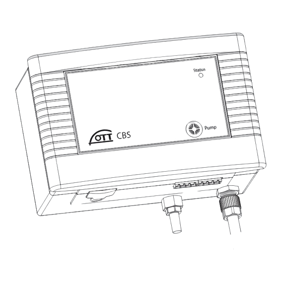
3 Introduction The OTT CBS, working on the air bubble principle, can be used for measuring ground water or water levels depending on the bubble chamber used. To meet the various demands of the station, three different versions of the OTT CBS bubble sensor are available: "Standard"... - Page 6 For the display of any error states that may occur, the OTT CBS has a "Status“ LED (see Fig. 1). Connection to a data logger can be established via a choice of SDI-12, RS-485 (2-wire; SDI-12- / Modbus protocol) or 4 …...
-
Page 7: Installing Ott Cbs
(see chapter 8). 4.2 Fastening OTT CBS The OTT CBS is designed only to be installed on top hat rails (a section of top hat rail is supplied with the OTT CBS). Choose a dry and dust free location for the installation such as a gage station or control cabinet. -
Page 8: Connecting Measuring Tube To Ott Cbs
4.3 Connecting measuring tube to OTT CBS To install the measuring tube on the OTT CBS, proceed as follows: Measuring tube with 2 mm internal diameter Cut off the end of the measuring tube square with a sharp knife and push onto the factory fitted connection nipple. -
Page 9: Installing Bubble Chamber
Do not damage or kink the measuring tube during installation. Lay the measuring tube such that there is a continuous drop from the OTT CBS towards the bubble chamber. Otherwise moisture could collect in a "hollow"... -
Page 10: Installing Bubble Chamber For Ground Water
5.2 Installing bubble chamber for ground water To install the bubble chamber for ground water, proceed as follows: Determine depth of the bubble chamber (e.g. using a contact gauge). The bubble chamber must be positioned under the lowest expected water level. Depth = distance from bubble opening to upper edge of the top cap Push the measuring tube into the cable gland of the bubble chamber as far as... - Page 11 As shown in Fig. 7, attach the suspension cable of the bubble chamber to the retainer on an OTT top cap already mounted. The retaining plate allows a fine height adjustment afterwards. Secure the suspension cable against slipping with a knot.
-
Page 12: Connecting Ott Cbs
(U + GND). The three interfaces make it possible to connect the OTT CBS both to OTT data loggers and to any data logger by another manufacturer that has the correct interfaces. Note that only one of the interfaces at a time can be used (no parallel operation of interfaces). -
Page 13: Connect Power Supply
6.1 Connect power supply The OTT CBS requires a power supply of 10 … 30 V DC, typ. 12/24 V DC (e.g. using batteries or mains connection with galvanically separated low safety voltage). Please note the following points when dimensioning the power supply: Maximum power consumption per day: 3700 mAh (typ. -
Page 14: Determining The Maximum Load Resistance At The 4 ... 20 Ma Interface
This value depends on the level of the supply voltage of the OTT CBS. If the load resistance is greater, the loop current* can no longer be evaluated. Smaller load resistances are allowed. -
Page 15: Activating The Purge Function
7 Activating the purge function On the front of the OTT CBS there is a "Pump" membrane button (see Fig. 10). Pressing the button activates the purge function for as long as it is pressed. The "Status" LED lights for approx. 2 seconds. With an activated purge function, the CBS pumps a large amount of air through the measuring tube for the required time period (see also chapter 11). -
Page 16: Adjusting Operating Parameters Using The Service Interface
8.1 Setting the serial interface type With DIP 1 … 3 select the type of SDI-12 interface of the OTT CBS (screw terminal strip B; contacts 1 to 4). Note that only one of the interfaces at a time can be used (4 ... -
Page 17: Setting Measurement Type Of The 4 ... 20 Ma Interface To Level Or Depth Measurement
With DIPs 5 and 6 you can scale the available measuring range (15 or 30 m) of an OTT CBS to a smaller range. Where the whole measuring range is not required, this has the advantage that a higher resolution for the 4 … 20 mA interface can be achieved. -
Page 18: Setting The Measuring System For The 4 ... 20 Ma Interface
8.4 Setting the measuring system for the 4 … 20 mA interface Fig. 14: Setting the measuring system of the OTT CBS (4 … 20 mA interface). 1 2 3 4 5 6 Metric measurement system: m + mbar 1 2 3 4 5 6 Imperial measurement system: feet + psi 8.5 Setting measurement type of the 4 …... -
Page 19: Sdi-12 Commands And Responses
All advanced, manufacturer-specific SDI-12 commands on the OTT CBS begin with "O" for OTT. With these commands it is possible to configure the OTT CBS, for example using the "Transparent mode" on a data logger or with the OTT USB/SDI-12 interface accessory. - Page 20 Advanced commands (manufacturer-specific) aOXM<value>! Set measuring time aOXM! Factory setting: +50 s Read measuring time aOXC<value>! Set cycle time aOXC! Factory setting: +60 s Read cycle time aOAA<value>! Set "level" or "depth" measuring mode aOAA! Factory setting: +0 Read measuring mode "Level"...
-
Page 21: Standard Commands
CRC value in this case: Do not use these commands if the OTT CBS is connected to a data logger using the 4 … 20 mA interface. This would cause the OTT CBS to interrupt the con- tinuous measurement mode, which is necessary for the 4 … 20 mA interface. - Page 22 – CRC value (only after aMC!, aCC!) atttn<CR><LF> Start system test – Sensor address – Time in seconds until the sensor OTT CBS response: 001 has determined the measured result OTT CBS response: 1 – Number of measured values a<value><CR><LF>...
-
Page 23: Meta Data Commands
(aV!) command. This command does not start a system test! aIM_001! a,<Field1>,<Field2>, … aIC_001! … <Field3>;<CRC><CR><LF> value <value1> The OTT CBS sends meta data for the associated measured in the form of three data fields. These aIMC_001! commands do not start any measurements! aICC_001! <Field1> – Measured value code –... -
Page 24: Advanced Sdi-12 Commands
Mobus protocol (aOPF! Time interval in which the OTT CBS starts measurements. With the 4 … 20 mA interface, the OTT CBS adjusts the loop current when the measured result is available. The con- dition "Cycle time ≥ Measuring time" must be met. If it is not, the OTT CBS automatically adjusts the measuring time to the cycle time. - Page 25 Measured value = +2.100 m Reference value = +1.500 m Output = +1.500 m (Offset calculated by OTT CBS and applied to all other measured values = +0,600 m) Note If the unit is subsequently changed (aOSU<value>!) you must reset the offset value...
- Page 26 – Sensor address +0.500000 … +2.000000 +1.000000 Value range: Factory setting: You can use this command to correct the pressure/level value. The OTT CBS multiplies the measured values by the correction factor. Set/read local acceleration due to gravity aOXG<value>! a<value><CR><LF> aOXG! a<value><CR><LF>...
- Page 27 9.80659 m/s Note The OTT CBS is preset to an average value for Germany (Kas- sel). The measured value variation caused by acceleration due to gravity in Germany is ±3 mm (Flensburg – Oberstdorf). This measured value error can be compensated by entering the local acceleration due to gravity.
- Page 28 V1.20.0) For example, the previous version of the SDI-12 interface is required if the OTT CBS is to be fitted in an existing installa- tion as a replacement device. This does not require a change in the configuration of the existing data logger.
-
Page 29: Carrying Out Maintenance Work
After 15 years' operation, test the measuring tube for tightness/pressure resis- tance roughly every 2 years. Never open the housing of the OTT CBS! There are no adjustment or control elements inside the housing! In the case of device defects, contact the OTT Repaircenter:... -
Page 30: Status" Led
→ the LED "Status" lights once for a longer period as confirmation → Pause → 1st error state arising (e.g. flashing once) → Pause → 2nd error state arising (e. g. flashing three times) → Pause → … . The OTT CBS repeats all error states arising for approx. two minutes. -
Page 31: Technical Data
13 Technical Data suring ranges "Standard" + "USGS specification" version 0 … 15 m or 0 … 1500 mbar 0 … 50 ft or 0 … 25 psi "30 m measuring range" version 0 … 30 m or 0 … 3000 mbar 0 …... -
Page 32: Appendix A – Connecting The Ott Cbs To Ott Netdl Or Ott Duosens Using The Sdi-12/Rs-485 Interface
SDI-12). The maximum length of the cable is 70 m. Recommended cable cross-section: 0.5 mm Connect the OTT CBS as shown in Figure 17 to the OTT netDL IP data logger or to the OTT DuoSens Compact data logger. Take note of the operating instructions for the OTT netDL/OTT DuoSens. - Page 33 Configuring the OTT netDL/OTT DuoSens for the OTT CBS with SDI-12 interface Create an OTT netDL/OTT DuoSens channel with "SDI-12 Master" or "OTT SDI RS485" function block ("Serial sensors" tab). Apply the following settings: Fig. 19: Adjusting the operating parameters of the OTT netDL/OTT DuoSens "SDI-12...
- Page 34 Therefore, three channels on the OTT netDL/OTT DuoSens are required to record the two measured values and the status of an OTT CBS. The first channel contains the "SDI-12 Master" or "OTT SDI RS485" function block as the input signal. The other channels each contain a "Virtual sensor"...
-
Page 35: Appendix B – Connecting The Ott Cbs To An Ott Netdl Or Ott Duosens Using The 4 ... 20 Ma Interface
Appendix B – Connecting the OTT CBS to an OTT netDL or OTT DuoSens using the 4 … 20 mA interface Connect the OTT CBS to the OTT netDL IP data logger or to the OTT DuoSens compact data logger as shown in Figure 20. Take note of the operating instruc- tions for the OTT netDL/OTT DuoSens. - Page 36 Insert a function block "2-point scaling" into this channel and set the appro - priate water levels for the electrical values measured (e. g. for an OTT CBS with 15 m measuring range and level measurement (DIP switches 5 + 6 = ON): Point 1: 4 →...
-
Page 37: Appendix C – Rs-485 Interface With Modbus Protocol (Rtu)
Appendix C – RS-485 interface with Modbus protocol (RTU) C.1 Prerequisites Connection using RS-485 interface (2-wire, half duplex, with termination), see chapter 6 SDI-12 command: aOPF<value>! Service interface setting DIP 1, 2 and 3: OFF OFF ON, see chapter 8.3 SDI-12 command: aOPG<value>! Modbus protocol activated Factory setting: deactivatet... - Page 38 C.3 "Read Input Register" function (0x04) Register name Register number Type Access mode Unit Level/depth/pressure measured value 0000 float m · cm · ft mbar · bar · psi Temperature measured value 0002 float °C · °F Status of last measurement 0004 float –...
-
Page 39: Appendix D – Note On The Declaration Of Conformity
Appendix D – Note on the declaration of conformity If required, you can download the current version of the declaration of conformity for the OTT CBS from our website as a PDF file: "www.ott.com/resources". - Page 40 OTT Hydromet GmbH Ludwigstrasse 16 87437 Kempten Germany ⋅ Phone +49 831 5617-0 +49 831 5617-2 09 Document number 63.200.001.B.E 05-0517 info@ott.com · www.ott.com...
Need help?
Do you have a question about the CBS and is the answer not in the manual?
Questions and answers