
Related Manuals for Bresser MCX Goto Series


Summary of Contents for Bresser MCX Goto Series
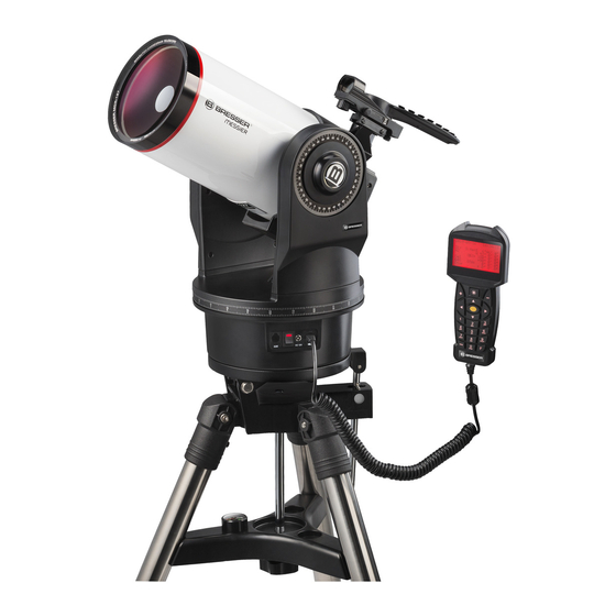
- Page 1 MCX Goto Series 102/1470 (4") · f/14.4 127/1900 (5") · f/14.9 Maksutov-Cassegrain GoTo telescope Art. No. 4701102 4701127 OPERATING INSTRUCTIONS...
-
Page 2: General Warnings
General warnings instructions carefully and do not attempt DANGER of material damage! to power this device with anything other Do not disassemble the device! In the This operating instruction than power sources recommended in this event of a defect, please contact your booklet is to be considered as manual, otherwise there is a DANGER OF A dealer. -
Page 3: Parts Overview
Parts overview Fig. 2 1& MCX GoTo Telescope (Fig. 2) 1. Eyepiece 10. Aux Input Port 17. Adjustment knobs for 2. LED viewfinder 11. Motor housing and mount base the LED viewfinder 3. S et screw for the eyepiece holder 12. Circular bubble level 18. Mount for the LED viewfinder 4. Eyepiece holder with 90° view 13. -
Page 4: What's Included
Assembly What’s Included: Fig. 3 The MCX is supplied as far as possible pre-assembled from the factory. You can start your observations in only a few minutes following these instructions carefully. When opening the package for the first time, check carefully that all the parts listed below are included (Fig. - Page 5 Assembly IMPORTANT NOTE! Fig. 8 Before each observation you should make sure that the tilting mirror is in the "UP" position (14, Fig. 2). For further information please refer to chapter "Operating the tilting mirror" on page 11. Assembling the MCX Telescope To operate the MCX, you need an additional eight AA batteries - the assembly takes place in just four steps: 1. M ount the LED viewfinder using the Allen key as shown in Fig. 8 shown on telescope tube. IMPORTANT NOTE! Make sure that the mirror surface of the LED viewfinder points towards the tube opening Installation of the LED viewfinder when attaching it.
-
Page 6: The Field Tripod
Superstructure The field tripod Fig. 11 With the field tripod a MCX telescope can be mounted in Alt/Az mode, as well as Equatorially. An equatorial wedge, comprising of a tilt plate and height adjustment bar, is built into the tripod The parts: - Tripod with attached tilting plate and height adjustment bar unit with clamp. - Page 7 Superstructure Alt/Az Positioning Fig. 15 The Alt/Az position of the telescope is ideal for quick observation of terrestrial and astronomical objects. The telescope is swivelled in horizontal and vertical direction. Alt/Az mounting of the telescope 1. L oosen the height adjustment bar clamping bolt (4, fig. 15) and adjust the tilt plate (2, fig. 15) facing slightly upwards so that you can easily reach the underside of the plate.
- Page 8 Use of the Special features of the telescope Practical Tips - Rotation limiter: The telescopic base and the mounting fork are equipped with an internal "rotation limiter". The horizontal turnstile prevents the telescope from turning by more than 630°. This avoids damage to the internal wiring. The vertical pan lock ensures that the viewfinder does not move against the mounting fork when the telescope is tilted beyond the vertical 90° position. It also ensures that the optical tube never touches the base as soon as you tilt it deeper than 30°. Never attempt to move the telescope beyond these locks manually or by motor drive.
- Page 9 NOTE! The AUX port (2, fig. 22) at the interface is foreseen for future developments, but not currently active. Unfortunately there are no accessories available at the moment. We may inform you about new developments for this product on our website at www.bresser.de/ download/Messier WATCH OUT! Use of unauthorized products may damage the telescope electronics and void your warranty.
- Page 10 Use of the Using the LED Viewfinder Fig. 23 The LED viewfinder projects a red dot onto the mirror surface (1, fig. 24) and thus "before" the target. This makes it easier to adjust objects. By turning the large knurled wheel, you can switch the LED viewfinder on or off and also adjust the brightness of the illuminated dot. The viewfinder is aligned with the small knurled wheels on the lower and left side.
- Page 11 Use of the The first night As a freshly baked telescope owner, she naturally wants to penetrate the depths of the universe immediately. Unfortunately, stargazing can only take place on clear nights. However, if the weather is not good, you still have some time to prepare for the first night. It makes sense if you are concerned with the construction of the device, which must also succeed in the dark.
-
Page 12: First Observations
Use of the First observations Fig. 25 There is a dust cap in front of the front lens of your telescope. At the same time, press the two locking buttons slightly inwards and remove the dust cap. The MCX is now ready for terrestrial observation. -
Page 13: Basic Knowledge
Basic knowledge Basic hints With the MCX telescopes you can start observing immediately after unpacking. However, if you have first familiarized yourself with the basics of using the telescope, a subsequent observation will be much easier and more rewarding. Eyepiece selection The task of a telescope eyepiece is to magnify the image produced by the telescope's main optics. - Page 14 Basic knowledge Magnification = -------------------------------- Eyepiece focal length Example: The magnification achieved by the MCX-127 in conjunction with the SP 26mm eyepiece is as follows: Fig. 26 1900 mm Magnification = -------------------------------- = 73x 26 mm Too much magnification: The most common mistake an inexperienced observer makes is to "over-zoom" the telescope - he uses too high magnifications that no longer match the telescope aperture and typical atmospheric conditions. Never forget that a smaller, but bright and well-resolved image is far superior to a larger image, which appears to be flat and poorly-resolved! See in this context the figure. 9 on. Magnifications beyond 250x should only be used when atmospheric conditions are exceptionally stable.
-
Page 15: Terrestrial Observations
Basic knowledge Telescope mounts The technical aids which ensure that the optical tube of a telescope can be moved in different directions are summarised under the term "telescope mount" or "mount". These telescopic mountings can be divided into two basic designs: Azimuth mounts allow the telescope tube to move vertically and horizontally. The MCX has an azimuthal mount (fig. - Page 16 Basic knowledge Astronomical Observations Once used as an astronomical instrument, the MCX offers numerous optical and electromechanical capabilities. And especially in these astronomical applications, the extraordinarily high degree of optical performance of the MCX is apparent at first glance. The abundance of observable astronomical objects, with less experience, is limited solely by the motivation of the observer.
- Page 17 Basic knowledge Sidereal tracking speed While the earth turns under the night sky, the stars seem to wander from east to west. The speed with which the stars move along is called "sidereal speed". If the telescope is aligned with the celestial pole (see previous chapter "Telescope mounts" on page 15), the motor drive of the MCX is designed so that the telescope rotates at sidereal speed.
-
Page 18: Celestial Coordinates
Alignment and Orientation Astronomical Observations Fig. 29 For extended astronomical observations, it is best to mount the telescope in the equatorial configuration. When aligned to the celestial pole, the telescope is oriented so that the horizontal and vertical axes of the telescope coincide with the coordinate system in the sky (see figure). 28 on page 15). - Page 19 Alignment and Orientation Fig. 31 All objects of the sky can thus be precisely defined by their celestial coordinates in right ascension and declination. Finding the celestial pole To get a rough idea of where the points of the compass are at an observation site, you Search map for the Polarstern.
- Page 20 Alignment and Orientation 11. S elect and execute the appropriate alignment method (see page 24). Optimized start position 1. Adjust the pole height on the tilting plate of the tripod as accurately as possible using a scale. 2. R elease the clamp of the height axis and set the scale to exactly 90° degrees and then tighten the clamp again slightly. 3. Turn on the LED viewfinder. 4. M ove the complete tripod until you can see the polar star centered in the viewfinder. The telescope then moves towards the sky in the direction of the polar star.
- Page 21 Computerised Handset with LED display The handheld computer Fig. 33 1. LCD display 2. ENTER key 3. MODE button 4. key + key 5. Arrow keys 6. Numeric keys 7. Stop button 8. Help button 9. C onnection socket for the spiral cable 10. Function key 11. Illumination button for the Taschenlampe 12.
- Page 22 Computerised Handset with LED display ferent options. You can also use the "Up" and "Down" keys to scroll through the letters of the alphabet or numeric digits. 6. Numeric keys (6, fig. 33) - Here you can enter the numbers 0 - 9 and change the ro- tation speed (for more information see "Rotation speeds") The "0" button can also be used to switch the red flashlight on the top of the handheld computer on and off. NOTE! 7. Stop button (7, fig. 33) - This interrupts any motor movement of the telescope. After In case of a malfunction of the pressing the button again, the telescope resumes the last executed function.
- Page 23 Computerised Handset with LED display Telescope control main menu - Alignment - one star Aim telescope at a star - two-star Align telescope to two stars - three-star Align telescope to three stars - dubbing Increases alignment accuracy - RA Spielausgl. RA Backlash compensation calibration - DEC Playlausgl.
-
Page 24: One-Star Alignment
Computerised Handset with LED display Initialization of the controller This chapter describes how to initialize the handheld computer. Perform this procedure either when you are using the handheld for the first time or when you have previously performed the RESET function (see "Resetting" on page 32). 1. M ake sure that the DEC and RA clamps (6 and 9, fig. 2) are tightened according to the instructions. - Page 25 Computerised Handset with LED display region to which the telescope points. Once you have adjusted the viewfinder telescope, NOTE! it will usually be the brightest star in the viewfinder's field of view. After the star is Once the telescope is aligned, move centered in the eyepiece field of view, press Enter.
-
Page 26: User Objects
Computerised Handset with LED display Navigation to the observation objects "Go To Saturn This exercise shows you how to select a celestial object, Saturn, for observation from the basic data of your handheld computer. 1. After the telescope is aligned, the main screen appears on the LCD of the handheld NOTE! computer. - Page 27 Computerised Handset with LED display 6. P ress ENTER. The telescope now moves to the previously stored object coordinates. The object is automatically tracked by the controller. After positioning, the object may not appear in the middle of the field of view of the telescope (eyepiece). Then center this object with the direction keys in the field of view. Land objects Unfortunately, this function is not yet available in the current software version! Accessories menu...
- Page 28 Computerised Handset with LED display LCD lighting Select this function to adjust the backlight of the screen. Use the up and down buttons to select the appropriate lighting level. Press the MODE button to return to the main menu. Telescope parking Select this function to move the telescope to the parking position (start position).
- Page 29 Computerised Handset with LED display Tracking speed Allows you to adjust the speed of the automatic tracking. Select the desired option and press ENTER. The following options can be set: Star Speed: Sidereal velocity / star velocity (default factory setting) Solar Speed: Speed of the sun Moon Speed: Moon speed Customize Speed: Unfortunately, this function is not yet available with the current...
- Page 30 Computerised Handset with LED display Fig. 35 - 30 -...
- Page 31 Appendix VIII How do I find the Polarstern? Fig. 36 Starting from the two "pointer stars" - the two rear stars of the car body - pull a fivefold extension up to the polar star. If you extend this line far beyond Polaris, you will reach the large square of stars shared by Pegasus and Andromeda. The summer triangle is a striking sky region to the left of the Big Dipper drawbar. This triangle consists of three very bright stars: Vega, Deneb and Atair.
- Page 32 Appendix VIII "You and the universe" The distance between Earth and Moon Distance = 383.000 km Earth Moon Diameter = 12.664 km Diameter = 3.456 km The distance between the planets Sonne The distance between Earth and Sun is 149 million km or 1 astronomical unit (AU). Remember Venus Earth Mars Distance to the sun = 0,39 AE Distance to sun = 0,72 AE Distance to sun = 1,00 AU Distance to the sun = 1.52 AU The elliptical orbit of Pluto is relatively eccentric and ensures that the Planet in its closest point to the sun is still within the Neptune orbit.
- Page 33 Appendix VIII Observation You should allow about 90 minutes for the temperature adjustment before observing. If the telescope is set up e.g. from a heated car or house on the free field, it can come to a so called "Tubus-Seeing". This results from the main mirror not yet adapted to the temperature difference. Only after the temperature adjustment the telescope shows a sharp picture. The first observations are best practiced during the day, so you will quickly become familiar with the operation of your new telescope.
- Page 34 Appendix VIII ring division within Saturn's rings, the so-called "Cassini division", can normally be seen in the telescope. Titan, the largest of Saturn's 62 moons, is also visible as a bright, star- shaped object not far from the planet. Under good visibility conditions, up to 6 Saturn moons can be observed in the telescope. Deep sky objects In order to find constellations, single stars or "deep sky objects", the use of a star chart is recommended. In the following, various examples of deep sky objects are listed: The stars are huge gaseous objects that glow independently because they generate energy in their centre through nuclear fusion.
- Page 35 Appendix VIII Some tips You will have noticed that objects observed through the telescope appear upside down and upside down. This is the case with every astronomical telescope for physical reasons and does not play a role in stellar observation. Due to the rotation of the earth, all celestial objects seem to move slowly through the visual field.
-
Page 36: Maintenance And Care
Maintenance and care If the air humidity is high, the glass may fog up and moisture may form. This is not a defect! In this case, allow the device to acclimatise at room temperature for some time so that the residual humidity can be reduced. Protect the device from dust and moisture! Keep it in the supplied bag or transport packaging. -
Page 37: Optional Accessories
Optional accessories BRESSER Plössl eyepieces BRESSER 12V power supply 2.0A f/5 mm Item no. 0455121 Item no. 4920205 (Ø 31.7mm, 1¼") f/6,5 mm Item no. 4920206 (Ø 31.7mm, 1¼") f/10mm Item no. 4920210 (Ø 31.7mm, 1¼") f/15mm Item no. 4920215 (Ø 31.7mm, 1¼") f/20mm BRESSER Item no. 4920220 (Ø 31.7mm, 1¼") 12V Automotive Power Cable, 7.5m f/25mm Item no. 4930100 Item no. 4920225 (Ø 31.7mm, 1¼") f/30mm Item no. 4920230 (Ø 31.7mm, 1¼") BRESSER Barlow lens 2x BRESSER Smartphone holder Item no. 4950110 Item no. 4910300... -
Page 38: Warranty And Service
EC declaration of conformity A "Declaration of Conformity" in accordance with applicable directives corresponding standards has been prepared by Bresser GmbH. This can be viewed at any time on request. - 38 -... - Page 39 - 39 -...
- Page 40 Bresser GmbH Gutenbergstr. 2 · DE-46414 Rhede Germany www.bresser.de · service@bresser.de...
Need help?
Do you have a question about the MCX Goto Series and is the answer not in the manual?
Questions and answers