Table of Contents
Advertisement
Advertisement
Table of Contents

Subscribe to Our Youtube Channel
Related Manuals for Olympus i-SPEED


Summary of Contents for Olympus i-SPEED
- Page 1 INSTRUCTIONS HIGH SPEED VIDEO CAMERA SYSTEM...
-
Page 3: Table Of Contents
......... Chapter 7 Understanding the Olympus i- SPEED . -
Page 4: Important Information - Please Read Before Use
The camera has a replaceable fuse on the rear panel and does not contain any other user-serviceable parts. Do not disassemble, modify or attempt to repair, user injury and/or equipment damage can result. Please contact Olympus for service/repair. Signal words The following signal words are used throughout this manual: Indicates a potentially hazardous situation which, if not avoided, may result in minor or moderate injury. - Page 5 Operating precautions Olympus will only be considered responsible for the safety, reliability and performance of the system if the following precautions are strictly adhered to: Do not operate the equipment in the presence of combustible gases or vapours. If in any doubt about the operating environment, contact Olympus.
- Page 6 Avoid subjecting the unit to heavy knocks or shock loadings, as these will reduce the effective life and reliability of the components within the unit. Before operating the unit, check that cooling vents are not blocked or obstructed. General notes S The i- -SPEED viewer software runs on Microsoft Windows 2000 or Windows XP.
- Page 7 Software will conform in all material respects to the user documentation furnished to you by Olympus. The sole responsibility of Olympus under this warranty will be, at its option, (1) to use reasonable efforts to correct documented errors in the Software that are reported to it within the forgoing warranty period or (2) to refund the License fee paid.
- Page 8 Software, or arising out of in connection with or relating to this License Agreement shall not exceed the License fee paid to Olympus by you for the Software. In no event shall Olympus or its suppliers be liable for any indirect, incidental, special, exemplary, or consequential damages (including any damages resulting from loss of use, loss of data, loss of profits or loss of business), or lost profits, even if Olympus has been advised of the possibility of such damages.
-
Page 9: Chapter 1 Introduction
Chapter 1 Introduction i- -SPEED The Olympus is a self--contained high speed video camera. This means that it contains all the functionality required to obtain high speed video and does not require the presence of a PC. The camera has... -
Page 10: Chapter 2 Checking The Package Contents
Checking the Package Contents Remove the transit sleeve and open the i- -SPEED system case. Match all items in the case with the items shown below. If any item is missing or damaged contact Olympus. Camera Trigger Switch Power Supply... -
Page 11: Chapter 3 Nomenclature And Functions
Nomenclature & Functions Chapter 3 Nomenclature and Functions Camera SVGA connector Fuse Power LED Power connector Composite video BNC connector Ethernet connector Feature connector Protective bar Controller connector PCMCIA slot for compact flash adaptor i- -SPEED... - Page 12 CDU. Although this connector conforms to the LVDS industry standard, it is recommended that only cables supplied by Olympus are used and it is imperative that no equipment other than the CDU is attached to this connector. i- -SPEED...
- Page 13 Nomenclature & Functions 6. Ethernet Connector Used for software updates if newer software becomes available. 7. SVGA Connector This connector provides a SVGA signal which contains the video image and overlay graphics. This signal is a copy of the CDU image. The output standard is the 60Hz SVGA PC video signal and the connector conforms to the PC video 15 pin D--sub standard.
- Page 14 Further details are provided in Chapter 7 “Understanding the Olympus i- -SPEED”. When the trigger is set to 0%, the trigger counter is set to the length of the memory, so that the trigger point appears at the beginning (0%) of the final video clip.
- Page 15 It is sometimes necessary to adjust the distance between the C--mount face and the image sensor to accommodate lenses from different manufacturers and lenses with different optical i- -SPEED tolerances. The Olympus has a back focus assembly located in the front of the unit to permit this adjustment.
- Page 16 Chapter 8 “Maintenance”. 15. Battery Memory i- -SPEED The Olympus contains a battery powered clock and memory. This is used to keep track of the time and date while the camera is switched off. The memory is also used to store some of the user controls, such as the TV monitor standard and the language setting.
-
Page 17: Power Supply/Mains Cable
Connects to the ‘power’ socket of the camera and provides power to the camera and its controller unit. The user must ensure that only the power supply unit supplied with the Olympus i- -SPEED is used and that this unit is only used to power the camera. -
Page 18: Controller Display Unit (Cdu)
Nomenclature & Functions Controller Display Unit (CDU) Controller cable connector Function keys Soft keys Strap Tripod mount Stand The CDU is not High--G rated. The CDU can be detached and reattached without switching the camera off. i- -SPEED... - Page 19 Nomenclature & Functions 1. CDU The CDU displays the image from the camera in real--time and permits the most flexible use of the camera, by using a series of buttons around the outside of the screen. The CDU is connected to the camera’s Controller connector via a 3m controller cable (a 10m cable is available as an optional accessory).
- Page 20 The CDU must not be connected to any i- -SPEED equipment other than the Olympus camera, otherwise equipment damage will occur. To maintain standards compliance, it is recommended that only cables supplied by Olympus are used.
-
Page 21: Chapter 4 System Connection
System Connection Chapter 4 System Connection Refer to the diagram shown below and connect the system. Optional PC/TV monitor Trigger switch Mains power cable CDU (Controller Display Unit) C- - Mount lens* Controller cable VGA cable * Camera Composite video BNC cable* Power supply unit (PSU) *not supplied in the standard set i- -SPEED... -
Page 22: Chapter 5 Getting Started
High speed video clips generally contain a large amount of “dead time” and a relatively small amount of useful motion, in recognition of this, the Olympus i- -SPEED has a clip select function which allows a precise choice of the video to be saved. -
Page 23: Controlling The Camera With The Cdu
Getting Started Controlling the camera with the CDU This section describes the basic steps required to start using the i- -SPEED camera system with the CDU. Additional information regarding functionality of the CDU can be found in Chapter Connect the system as described in Chapter 4, then connect the mains power cable to a suitable AC wall outlet and switch the... - Page 24 Getting Started Once the camera has been switched on, the image will contain fixed noise. This must be removed by pressing “Config” then “Calibrate sensor”. Immediately the “Calibrate sensor” button is pressed, the lens must be completely covered to provide total darkness to the sensor for the duration of the process.
- Page 25 Getting Started When recording has stopped, whether by trigger or STOP button, the camera will present the Player menu and display the first recorded image in the memory. Player controls are: jump back, play backwards, play forwards, jump forward (to bookmark). Each button when pressed changes to a Stop button.
- Page 26 Getting Started Use the up/down buttons on the right hand side of the CDU to adjust playback speed. If the video clip is to be saved, insert a PCMCIA memory card into PCMCIA slot in the camera. Use the player controls to navigate to the desired start position. Press Clip select and press Clip start.
-
Page 27: Chapter 6 Embedded Software Reference (Cdu)
Software reference CDU Chapter 6 Embedded Software Reference (CDU) Introduction ’ This reference section describes the camera s embedded software and its user interface from the viewpoint of the CDU. In this section, items which are printed like this signify the name of a sub menu, controls are described whenever they appear in a menu. -
Page 28: Menu Screens
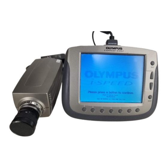
Software reference CDU Menu Screens OLYMPUS i- -SPEED Splash Screen This screen is displayed while the camera starts up and configures the internal software. It contains data on the memory configuration of the camera, the serial number and the software version number. - Page 29 SVGA display specification. The maximum speed is fixed to 1,000fps. As described in Chapter 7 “Understanding the Olympus i- -SPEED”, the user will normally need to open the iris of the lens and/or add more light as the speed is increased.
- Page 30 An on screen message shows the status of the white balance process. Please refer to Chapter 7 “Understanding the Olympus i- -SPEED” for a further description. Once this is set, the white balance setting is stored in the camera’s internal memory.
- Page 31 Software reference CDU Recording Menu When this menu is displayed, the Olympus i- -SPEED is recording video into its circular buffer. The record action is confirmed by the presence of a small animated camera icon. When a trigger signal is received and the camera is working through the length of its ’...
- Page 32 Software reference CDU Player Menu This specialised screen allows the user to play back and interact with the video stored in the circular buffer memory. Access: i- -SPEED Home Playback Options: Jump back Reverse play Forward play Jump forward Clip select Bookmark The CDU will display the playback images required by the player controls ` Player Controls...
- Page 33 Software reference CDU ` On Screen Information The player provides a progress bar at the top of the screen to indicate the relative position within the circular buffer of the currently displayed frame. This bar is also used to display bookmarks.
- Page 34 Software reference CDU Card Management Menu This menu makes available the items which relate to the management of the PCMCIA removable memory card, both ATA and Compact FLASH. The screen includes a list of the files on the card and one of these will be highlighted by a selection bar.
- Page 35 Software reference CDU Config Menu This menu makes available all the items which relate to the configuration of the camera. Access: i- -SPEED Home Config Menu Options: Time/Date Language TV Monitor Calibrate Sensor Trigger edge Trigger pos ` Language Control This control permits the user to set the language in which the menus are displayed.
- Page 36 Software reference CDU ` Calibrate Sensor Control In common with all CMOS sensor chips, the Olympus i- -SPEED sensor requires a calibration system to remove fixed pattern noise. The Olympus i- -SPEED provides an off--chip calibration system. To calibrate the sensor, the user must press the “Calibrate” button and then completely cover the lens to exclude all light.
- Page 37 Software reference CDU Clip Select Menu This menu makes available all the items which relate to selecting the video clip to be saved on the PCMCIA card. Access: i- -SPEED Home Playback Clip select Options: Clip start Clip end Card Save The CDU will display the playback images required by the clip select controls ` Player...
- Page 38 Software reference CDU ` On Screen Information The Clip Select menu provides a progress bar to indicate the position in the buffer memory of the currently displayed frame as well as the start and end frame markers. This bar is also used to display bookmarks.
-
Page 39: Chapter 7 Understanding The Olympus I- Speed
Understanding the Olympus i- SPEED The Olympus i- -SPEED has been designed with ease of use in mind and all the functions of the camera are accessed via clear and descriptive menus. Every effort has been made to ensure that the menus are intuitive. - Page 40 The method of stopping the camera is highly important as it is this which guarantees the capture of the event in question. There are two methods of stopping the Olympus i- -SPEED . The first is a button press in the menu system and this immediately stops the record process, so that the memory contains the history prior to the button press.
- Page 41 Since the trigger is an electrical signal, the Olympus i- -SPEED may be set to wait for either the rising or the falling edge of the trigger pulse.
- Page 42 ` Lighting The Olympus i- -SPEED has been designed to remove most of the difficulty associated with taking high speed video shots, but two areas of critical importance still remain, lenses and lighting. In...
- Page 43 Understanding i- -SPEED ` View Finder In contrast with some other manufacturer’s products, the Olympus i- -SPEED camera presents the live image on the CDU or monitor screen at all possible times. Some menus do require the image to be obscured and the splash screen logo is used for this purpose.
- Page 44 It is not possible to specify an ideal lens, because photography is dependant on the object being photographed, but an “average” lens for the Olympus i- -SPEED would have a focal length of 25mm and an iris range of f/1.4 to f/22.
-
Page 45: Chapter 8 Maintenance
Maintenance Chapter 8 Maintenance Cleaning To prevent electric shock or damage to equipment, always disconnect from the power supply before attempting to clean. Camera CMOS protective glass and CDU screen Clean using lens tissues moistened with a solvent solution composed of 70% ether / 30% industrial methylated spirits. DO NOT use hard or abrasive materials. -
Page 46: Chapter 9 Spares And Accessories
Compact Flash Card -- 1Gb ....... . . 1163123 In addition to the above items, a range of flash cards, tripods, lenses and lighting equipment is also available, along with three PC software options, Basic, Advanced and Deluxe. Please contact Olympus for further information. i- -SPEED... -
Page 47: Chapter 10 Specifications
Specifications Chapter 10 Specifications 10.1 i- SPEED Camera ` Camera physical Dimensions Size W 106mm x H 98mm x L 264mm nominal Weight 2kg nominal Mechanical connections Tripod mounting 1x standard tripod mount (¼” Whitworth thread) Lens mounting Standard C--mount Back focus Nominal position 17mm. - Page 48 Specifications Ethernet RJ45: Used for software update if further releases become available Pinout TXD1+ TXD1-- RXD2-- RXD2+ Ethernet signal 10 / 100 Base--T, auto switching Link (in RJ45) Link status is indicated by two bi--colour red--green LED’s: Top red: 100Mb connection, half--duplex link Top green: 100Mb connection, full--duplex link Bottom red: 10Mb connection, half--duplex link Bottom green: 10Mb connection, full--duplex link...
- Page 49 Specifications ` Performance characteristics Resolutions, speeds & record times Sensor CMOS Resolution 800 x 600 active pixels Frame rate Maximum: 1,000 fps Minimum: 60 fps Nominal values of speeds and resolutions Resolution Pixels Frame Images in Record per frame speed Memory time 480000...
- Page 50 Auto white balance, single shot operation, no time limit on hold, and pre--set options Range To correct for daylight, fluorescent light, 60W mains tungsten (Anglepoise) and the full range of Olympus light sources. PCMCIA card interface File type The video will be saved in “*.AVI” and “*.BMP” format,...
- Page 51 Specifications 10.2 Controller Display Unit (CDU) Dimensions Size W 273mm x H 214mm x D 51mm nominal Weight 1.5kg nominal Stand A flip--out stand with ratchet positions of: --3_, 42_, 87_, 132_, 177_. When in the 177_ position, the stand can be used as a hanger Connector Type Standard LVDS connector, 26 way MDR...
- Page 52 Specifications 10.4 Power supply Dimensions Size 130mm x 58mm x 30mm nominal Weight 0.4kg nominal Mains input Socket type Fuse Internal, not user replaceable Power output Lead length 2.2m nominal Connector Lemo FGG.OB.304.CLAD52Z Electrical 100–240VAC ± 10%, 50--60Hz Input Output 12VDC, 36W minimum 10.5 Trigger switch Dimensions...
- Page 53 Specifications 10.6 Regulatory Status This mark on the i- -SPEED camera indicates conformity with the requirements of EC Directives 89/336/EEC relating to electromagnetic compatibility and for the 12V DC power supply, compliance with Directive 73/23/EEC, as amended by 93/68/EEC, relating to electrical equipment designed for use within certain limits (Low Voltage Directive).
- Page 54 Refer to your local Olympus distributor for return and/or collection systems available in your country. The Olympus i- -SPEED is Made in the UK by KeyMed, an Olympus group company. i- -SPEED...
- Page 56 OLYMPUS DEUTSCHLAND GMBH (Premises/Goods delivery) Wendenstrasse 14-18, D-20097 Hamburg, Germany (Letters) Postfach 10 49 08, D-20034 Hamburg, Germany Telephone: (040) 237730 OLYMPUS SURGICAL & INDUSTRIAL AMERICA INC. One Corporate Drive, Orangeburg, N.Y. 10962, U.S.A. Fax: (845) 398-9444 Telephone: (845) 398-9400 KEYMED LTD.
Need help?
Do you have a question about the i-SPEED and is the answer not in the manual?
Questions and answers