Table of Contents
Advertisement
Quick Links
Advertisement
Table of Contents

Subscribe to Our Youtube Channel
Related Manuals for Pittway Notifier RPT-485W


Summary of Contents for Pittway Notifier RPT-485W
- Page 1 12 Clintonville Road Northford, CT 06472 203/484-7161 FAX: 203/484-7118 The RPT-485W/RPT-485WF EIA-485 Annunciator Loop Repeater for Twisted Pair Wiring/Fiber Optic Cable Document 15640 08/13/97 Revision: 15640:B1 ECN 97-294 www.PDF-Zoo.com...
- Page 2 www.PDF-Zoo.com...
-
Page 3: Table Of Contents
Contents Section One: Introduction ..................4 Isolated System with Remote Supplies ..........4 Section Two: RPT-485W ..................5 Parallel/Series Connection of RPT-485Ws ........6 Section Three: RPT-485WF ..................7 Parallel/Series Connection of RPT-485WFs ........8 Section Four: Installation ..................9 Mounting ................... -
Page 4: Section One
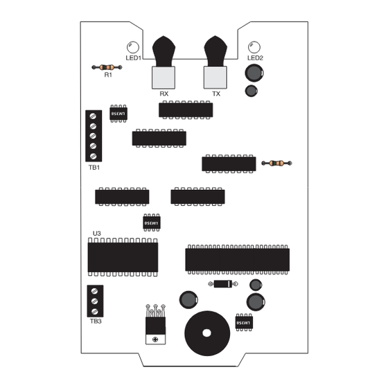
Section One: Introduction The RPT-485W/RPT-485WF ACS annunciator loop repeaters are designed to boost the EIA-485 annunciator signal from the fire alarm control panel (FACP). The RPT-485W is a repeater which supports twisted pair wire only; the RPT-485WF supports fiber optic cable between two repeaters. Any Notifier FACP that has an EIA-485 annunciator loop can employ RPT-485s. -
Page 5: Section Two
Section Two: The RPT-485W Purpose The RPT-485W is an ACS annunciator loop repeater for twisted pair wiring which extends the loop length and node capacity of the EIA-485 Annunciator Loop. The RPT-485W electrically isolates the EIA-485 Annunciator Loop. Features Extends EIA-485 distances in 4000 ft. increments. Allows additional boosted EIA-485 loops. -
Page 6: Parallel/Series Connection Of Rpt-485Ws
Two RPT-485Ws In Series Configuration In order to further extend the EIA-485 loop, 2 RPT-485s can be arranged in a series connection. Between the two RPT-485s, 32 EIA-485 devices, 32 RPT-485s, or a combination of both can be hung from the loop. The source EIA-485 loop can extend up to 6,000 feet and have 32 EIA-485 devices (including the RPT-485s) hung from it. -
Page 7: Section Three: Rpt-485Wf
Section Three: RPT-485WF Purpose The RPT-485WF is used to provide fiber optic capability, which may be necessary in environments exposed to strong electromagnetic interference such as power plants and areas with frequent lightning or in areas where a high level of security is required. The RPT-485WF optically isolates the EIA-485 annunciator loop eliminating ground loops and noise. -
Page 8: Parallel/Series Connection Of Rpt-485Wfs
Wiring RPT-485WFs The RPT-485WFs must be used in pairs. The source EIA-485 loop can extend up to 6,000 feet and have 32 EIA- 485 devices (including the RPT-485s) hung from it. An example of wiring an EIA-485 loop using RPT-485WFs is pictured in Figure 3-2. -
Page 9: Section Four
Section Four: Installation Installation The RPT-485W/RPT-485WF board can be mounted in a listed CHS-4, CHS-4L, or an ABS-8R (remote). When mounting on a CHS-4L, use the inner position. When the RPT-485WF is mounted on the CHS-4 and CHS-4L, adequate clearance above the board is required. Outer position mounting on the CHS-4 is also possible but the board has to be mounted with components facing inward. - Page 10 ABS-8R Mounting Before mounting the ABS-8R, determine which knockouts are needed to wire the RPT-485. If you are using an RPT-485WF, you must use the center top knockout for the fiber optic cable. Remove knockouts. Mount the ABS-8R. Place the RPT-485 in the box and afix into PEM standoffs using (4) 4-40 screws (refer to Figure C).
-
Page 11: Wiring The Rpt-485W
Use a power limited supply Use a power limited supply Figure 4-1: Wiring the RPT-485W NOTE: For EIA-485 device terminals connections, see Table 4-1. Document 15640 Rev B1 08/13/97 P/N 15640:B1 www.PDF-Zoo.com... -
Page 12: Wiring The Rpt-485Wf
Use a power limited supply Use a power limited supply Figure 4-2: Wiring the RPT-485WF NOTE: For EIA-485 device terminal connection, see Table 4-1. Document 15640 Rev B1 08/13/97 P/N 15640:B1 www.PDF-Zoo.com... -
Page 13: Connections Between The Rpt-485 And Eia-485 Devices
Table 4-1: Connections between the RPT-485 and EIA-485 Devices NOTE: For additional information, reference the respective manuals listed in Table 4-2. Table 4-2: EIA-485 Device Manuals Document 15640 Rev B1 08/13/97 P/N 15640:B1 www.PDF-Zoo.com... -
Page 14: Section Five
Section Five: Power Supply Specifications A power limited power supply, listed for Fire Protection Signaling, (may be located remotely) with both Primary and Secondary power, must be used for Fire Protective Signaling Applications. Operating Voltage Range 18-28 VDC Maximum current draw; (All states) RPT-485W 0.047 A RPT-485WF... -
Page 15: Main Facp Wiring For Power
All EIA-485 loops in this Figure share a common reference and are not isolated from each other (see Note 3). Figure 5-1: Main FACP Wiring for Power NOTES: ) For connections between the RPT-485 and EIA-485 devices, refer to Table 4-1. 2) For connections between the RPT-485 and EIA-485 sources, refer to Table 5-2. -
Page 16: Power/Reference Wiring For A Remote Rpt-485
Isolated Earth Fault Disabled Figure 5-2: Power and Reference wiring for a Remote RPT-485 NOTES: 1) A remote CAB-3 containing an RPT-485 must be connected to the SLC loop via an MMX and MPS-TR for detection of troubles. Refer to the MPS-TR Product Installation Drawing, Document 15331 for specific terminal connections. -
Page 17: Power/Reference Wiring For Multiple Rpt-485S
All EIA-485 loops in this Figure are isolated from each other. Figure 5-3: Power/Reference Wiring for Multiple RPT-485s NOTE: Most EIA-485 devices and sources manufactured by Notifier are not isolated. When making refer- ence connections to non-isolated EIA-485 devices powered by separate power supplies, care must be taken to ensure that only one power supply has Earth Fault detection enabled within a group of power supplies sharing the same reference connection. - Page 18 Notes Document 15640 Rev B1 08/13/97 P/N 15640:B1 www.PDF-Zoo.com...
- Page 19 Notes Document 15640 Rev B1 08/13/97 P/N 15640:B1 www.PDF-Zoo.com...
- Page 20 Limited Warranty ® NOTIFIER warrants its products to be free from defects in materials and workmanship for eighteen (18) months from the date of manufacture, under normal use and service. Products are date stamped at time of manufacture. The sole and exclusive obligation ®...
Need help?
Do you have a question about the Notifier RPT-485W and is the answer not in the manual?
Questions and answers