Table of Contents
Advertisement
I
NSTALLATION
NSW (Head Office)
7 Columbia Court
Norwest Business Park
Baulkham Hills NSW 2153
Ph:
(02) 9899-4155
Fax:
(02) 9899-4156
Notifier Inertia Pty Ltd (A.C.N 002 692 962)
A PITTWAY COMPANY
A PITTWAY COMPANY
www.inertia.com.au
Technical Manuals Online! - http://www.tech-man.com
A
AFP-300/400
P
ND
ROGRAMMING
S
QLD
16 Lucy St
Moorooka
Qld 4104
Ph:
(07) 3892-6444
Fax:
(07) 3892-6455
I
NTELLIGENT
D
ETECTION AND
A
LARM
V
OFTWARE
R
EVISION
VIC
Unit 2 297 Ingles St
Port Melbourne
Vic 3207
Ph:
(03) 9681-9929
Fax:
(03) 9681-9930
M
ANUAL
F
IRE
S
YSTEM
2.2
ERSION
AUS 3
Advertisement
Table of Contents

Related Manuals for Pittway Notifier Inertia AFP-300


Summary of Contents for Pittway Notifier Inertia AFP-300
- Page 1 Baulkham Hills NSW 2153 Qld 4104 Vic 3207 (02) 9899-4155 (07) 3892-6444 (03) 9681-9929 Fax: (02) 9899-4156 Fax: (07) 3892-6455 Fax: (03) 9681-9930 Notifier Inertia Pty Ltd (A.C.N 002 692 962) A PITTWAY COMPANY A PITTWAY COMPANY www.inertia.com.au Technical Manuals Online! - http://www.tech-man.com...
-
Page 2: Table Of Contents
AFP 300/400 I NSTALLATION ROGRAMMING ANUAL Installation ........................... 4 ............................4 VERVIEW Passwords..............................4 Operating Features ............................ 4 Basic System Requirements (SPECS) ...................... 5 AFP-400 System Diagram .............................5 AFP-300/400 Basic termination points.........................5 Panel Primary requirements Compatible System Components: ......................6 Compatible Annunciators........................... - Page 3 AFP 300/400 I NSTALLATION ROGRAMMING ANUAL Programming ........................20 ............................20 VERVIEW Turning the Panel on for the first Time How to enter a ‘Default’ Program....................... 20 Program Mode Screen ..........................21 Clear Program............................21 Autoprogram .............................. 21 Duplicate (Dual) Addressing..........................22 Default Autoprogram Screen..........................23 Autoprogram Defaults ............................23 Autoprogram- Device no longer needed ....................
-
Page 4: Installation
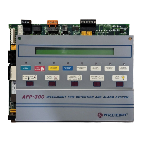
AFP 300/400 I NSTALLATION ROGRAMMING ANUAL Installation Overview The AFP-400 is a modular, intelligent Fire Alarm Control Panel (FACP) with an extensive list of powerful features. The CPU module, power supply module, and cabinet combine to create a complete fire control system for most applications such as commercial, residential and industrial buildings. -
Page 5: Basic System Requirements (Specs)
AFP 300/400 I NSTALLATION ROGRAMMING ANUAL Basic System Requirements (SPECS) The following section covers the suggested installation methods for the AFP-300/400. These are typical installation methods, and may not cover everything needed, Contact the Manufacturer for any additional information or assistance needed. AFP-400 System Diagram Loop 1 Loop 2... -
Page 6: Panel Primary Requirements
AFP 300/400 I NSTALLATION ROGRAMMING ANUAL Panel Primary requirements AC Power Requirements Basic System 240VAC, 1.5A Battery (sealed lead acid only) Dual Rate Charger High Charge 29.1VDC Normal Rate 27.6VDC Charging Current 2.0 A max, 1.5 A typical Battery Capacity: 55AH in larger Cabinet, 12AH mounted in CAB-AA 24Vdc Power Supply: Max. -
Page 7: Compatible Annunciators
AFP 300/400 I NSTALLATION ROGRAMMING ANUAL Compatible Annunciators ACM-16AT - Contains 16 red alarm and 16 yellow LEDs, and a local piezo sounder, Includes 16 switches for control panel functions. AEM-16AT - Expands the ACM-16AT by 16 system points per unit, up to a maximum of 64 points per address. -
Page 8: The Power Supply Connections
AFP 300/400 I NSTALLATION ROGRAMMING ANUAL The Power Supply Connections 240Vac- 24Vdc (Resettable/Non resettable) and Battery Connections The connections for the 240Vac and the 24Vdc Battery connections are indicated in the following illustration. MPS-400 - Terminal TB2 Non-resettable power Terminal 1(+) & 2(-) Circuit 1 AFP-300/400 Power Supply Non-resettable power Terminal 3(+) &... -
Page 9: Output Relays (On The Power Supply)
AFP 300/400 I NSTALLATION ROGRAMMING ANUAL Output Relays (on the power Supply) The control panel provides four monitored output circuits. Each circuit can Provide 2.5 amps of current. Total current drawn from the MPS-400 cannot exceed 6.0amps total. Relay 2 Relay 1 B+ B- A+ A- B+ B- A+ A-... -
Page 10: Rs-232 And Rs-485 Circuits
AFP 300/400 I NSTALLATION ROGRAMMING ANUAL RS-232 and RS-485 Circuits The AFP-300/400 has multiple RS-232 and RS-485 circuits; the illustrations below show the positions and where to find them. Wiring for RS-485 Annunciator Circuits Terminal Mode (LCD-80/LCD-80TM) - The AFP-400 provides Terminal Mode for high- speed two-way communication link to multiple Annunciators. -
Page 11: Rs-485 Terminal & Acs Connectors
AFP 300/400 I NSTALLATION ROGRAMMING ANUAL RS-485 Terminal & ACS Connectors Return Output LCD-80 Terminal Mode Connections ACS EIA-485 Connections EIA- AFP400 to LCD-80 Terminal Mode Connections AFP 400 End (TB3 Terminal Mode Output) LCD-80(TM) End (TB2) RS 485 IN + RS 485 OUT + (Terminal 1) RS 485 IN - RS 485 OUT –... -
Page 12: Remote Terminal Connections
AFP 300/400 I NSTALLATION ROGRAMMING ANUAL Remote Terminal Connections DB-25 connector CRT DB-9 CRT DB-25 AFP400(TB2) TX (Pin 2) TX (Pin 3) TB2-1 RX (Pin 3) RX (Pin 2) TB2-2 REF (Pin 5) REF (Pin 7) TB2-3 RS485 RS485 TX RX REF TX RX REF TERM IN TERM OUT PC/TERMINAL... -
Page 13: Analogue Loop Overview
AFP 300/400 I NSTALLATION ROGRAMMING ANUAL Analogue Loop Overview Communication with intelligent and Addressable devices occurs thorough a Signalling Line Circuit (SLC) Loop. You can wire an SLC loop in Style 4, Style 6 or Style 7 wiring. The AFP-300 control panel capacity includes up to 99 intelligent detectors, and an additional combination of up to 99 Addressable modules, (control modules and monitor modules). -
Page 14: Style 6 Loop Wiring
AFP 300/400 I NSTALLATION ROGRAMMING ANUAL Style 6 Loop Wiring Style 6 Wiring is a closed loop wiring method. Total cable length must be < 3,000 mtrs. Maximum impedance 20 ohms End to end of each wire (40 ohms total) Wire size .75mm2 twisted minimum 2 3 4 5... -
Page 15: Wiring Devices On The Loop
AFP 300/400 I NSTALLATION ROGRAMMING ANUAL Wiring devices on the Loop Please Note; Some of the wiring methods used in this manual only apply to the AFP-300/400, do not adopt these methods on other systems. Wiring Analogue Addressable Detectors Note: If optional shield used, do not connect to the spare terminal on the detector base, join the shield and insulate it from the other cables. -
Page 16: Wiring Control Modules (Cmx-2)
AFP 300/400 I NSTALLATION ROGRAMMING ANUAL Wiring Control Modules (CMX-2) CMX-2’s are used for Bells, Solenoids or any general relay application and can be monitored outputs or relay outputs. Wiring Short Circuit Isolator Modules (ISO-X) Note: When using the ISO-X module, limit the devices between each ISO-X to 25 devices. -
Page 17: Xp-5M & Xp-5C Modules
AFP 300/400 I NSTALLATION ROGRAMMING ANUAL XP-5M & XP-5C Modules The XP-5 Control and XP-5 Monitor modules are 5 separate modules and addresses mounted on one circuit card, the address is chosen by one rotary switch and one slide switch. The rotary switch selects the address in increments of ten, and the slide switch selects either 0 or 5. -
Page 18: Common Fault Finding Techniques
AFP 300/400 I NSTALLATION ROGRAMMING ANUAL Common fault finding techniques For a Loop that is wired in Twisted Shielded Pair: Shield Termination Connect to Enclosure Prior to connection, Loop+ check with VOM for external grounds. Loop - If Using optional shielded twisted pair cable to minimise radiated emissions of radio frequency energy, do not allow the shield drain wire to enter the cabinet. -
Page 19: The Affects Of Capacitance On Ground Faults
AFP 300/400 I NSTALLATION ROGRAMMING ANUAL The Affects of Capacitance on Ground Faults Capacitance can be a major cause of induced ground faults. If the capacitance between the conductors and earth ground exceed a certain value, the capacitive reactance (Xc) will fall below the ground fault circuit threshold, and a ground fault condition will occur. -
Page 20: Programming
AFP 300/400 I NSTALLATION ROGRAMMING ANUAL Programming Overview The AFP-300/400 is 100% field programmable, and has the added versatility of the Autoprogram feature, the Panel can also be programmed using a Laptop Computer. Turning the Panel on for the first Time After system power up is completed, the display message will be: Note: This would be for a new Unprogrammed AFP-300/AFP-400 panel CHECKING MEMORY-AFP-400/300 Release 2.2... -
Page 21: Program Mode Screen
AFP 300/400 I NSTALLATION ROGRAMMING ANUAL Program Mode Screen 0=CLR 1=AUTO 2=POINT 3=PASSWD 4=MESSAGE 5=ZONES 6=SPL ZONES 7=SYS 8=CHECK PRG (This is the Program Mode Screen, referred to often in this section of the manual). In program mode, the control panel: •... -
Page 22: Duplicate (Dual) Addressing
AFP 300/400 I NSTALLATION ROGRAMMING ANUAL If devices are installed and are programmed into the Panel, when the Autoprogram function is completed the screen will display the following; L1:02 Dets, 02 Mods L2:00 Dets, 00 Mods Panel Outputs: Bells: L1:, L2: = the number of detectors and modules connected to each Loop Panel outputs: -- (Not Used) BELLS: = the number of panel bell circuits always equal to “04”. -
Page 23: Default Autoprogram Screen
AFP 300/400 I NSTALLATION ROGRAMMING ANUAL After rectifying the Dual address, go back to the Autoprogram mode, and carry out another Autoprogram to find the device. In Program Mode select 1=Auto. the screen will then come back with the device that was last installed or address had changed. -
Page 24: Autoprogram- Device No Longer Needed
AFP 300/400 I NSTALLATION ROGRAMMING ANUAL Autoprogram- Device no longer needed If a detector exists in the control panel program, but is missing (no response from the device), the control panel will display the following: PROGRM SMOKE(PHOTO) DETECTOR ADDR 133 DEVICE NOT ANSWERING DELETE FR MEM? D133 To delete the device, press <ENTER>... -
Page 25: Editing Multi Detector Mode
AFP 300/400 I NSTALLATION ROGRAMMING ANUAL Editing Multi Detector Mode Multi detector mode Uses Adjacent Addresses Select Address above or below or both (both shown below). The chamber values are added, and when the total reaches 100% an alarm condition is displayed. The chamber with the highest reading will be the alarm point. -
Page 26: Delete A Point
AFP 300/400 I NSTALLATION ROGRAMMING ANUAL Delete a Point At the Edit point screen select 2=DELETE POINT, the screen now asks you to choose which point you want to delete. Example: Press Detector then the address <1>-<0>-<1>-<ENTER> the screen now asks: ENTER TO DELETE OR ESCAPE TO ABORT D101 Pressing <ENTER>... -
Page 27: Zone Labels
AFP 300/400 I NSTALLATION ROGRAMMING ANUAL Zone Labels The Zone option lets you change the custom label assigned to zones 1-99. From the Program Mode Screen, select <5> to display the Zone Change Screen. CHANGE ZONE LABEL SELECT ZONE 01-99: ENTER UP TO 19 CHAR The zone number displays on the first line For single digit numbers, enter a leading zero before the digit... -
Page 28: F5-F6 (Time Control)
AFP 300/400 I NSTALLATION ROGRAMMING ANUAL F5-F6 (TIME CONTROL) TIME FUNCTIONS TIME CONTROL ON = **:** OFF = **:** DATES = ******** Selecting F5-F6 screen provides field for changing the start time, stop time, or days of the week. From Special Zone Change screens, select F5 or F6 to display the Time Control screens.. TIME FUNCTIONS TIME CONTROL... -
Page 29: System Functions
AFP 300/400 I NSTALLATION ROGRAMMING ANUAL System Functions The System option lets you set general system functions. From the program mode screen, select <7> to display the System Functions screen: SIL INH=000 AUTO=000 VERIFY=30 AUS TIME TERM_SUPERV=NO LocT BLINK=Y ST=4 ACS=N System Function Setting... -
Page 30: Annunciator Selection
AFP 300/400 I NSTALLATION ROGRAMMING ANUAL Annunciator selection Selecting ACS=Y will display the Annunciator Selection Screen ANNUN SELECTION A1=* A2=* A3=* A4=* A5=* A6=* A7=* A8=* A9=* A10=* UDACT=N Use the Annunciator Selection screen to select the information that will display on the ACS annunciators. -
Page 31: Annunciator Group 2
AFP 300/400 I NSTALLATION ROGRAMMING ANUAL Annunciator Group 2 ACS Point Point Red LED Yellow LED Switch Number Type 1 to 43 Input Zone 57 to 99 Zone 57 to 99 Not used Active Fault 44 to 52 Output Zones F1 to F9 Zones F1 to F9 Not used Active... -
Page 32: System Check Function
AFP 300/400 I NSTALLATION ROGRAMMING ANUAL System Check Function When finished programming use the Check option to search the program entries for possible errors. From the program mode screen, select <8> to check the system program, the screen will now show: PRORAM CHECK OK. -
Page 33: Isolate A Device Or Zone
AFP 300/400 I NSTALLATION ROGRAMMING ANUAL Isolate a Device or Zone Select <1> from the Status Change screen to display the ISO/DE-ISO Screen ZONE=Z,AA,E DETECTOR=*,AAA,E MODULE=#,AAA,E Enter the address of the point, then press <ENTER>. Example:- Select the point type: * for detectors Then Press <1>-<0>-<1>-<ENTER>... -
Page 34: Clear History
AFP 300/400 I NSTALLATION ROGRAMMING ANUAL Clear History Select <4> from the Status Change screen to display the Clear History screen: PRESS ENTER CLEAR HISTORY FILE ESCAPE ABORT Pressing <ENTER> will clear the contents of the history file and return to the Status Change screen, or Pressing <ESC>... -
Page 35: Type Codes (Id's)
AFP 300/400 I NSTALLATION ROGRAMMING ANUAL Type Codes (ID’s) Please Note: when installing detectors the panel will determine the Type code for that detector, when installing modules, the panel gives a default Type Code, and then the programmer can determine what Type Code suits the application. The following section shows a table of the different Type Codes used for Monitor modules and Control Modules. -
Page 36: Control Module's
AFP 300/400 I NSTALLATION ROGRAMMING ANUAL Control Module’s To install a point see Autoprogram, To modify a point, See Edit point. Programming control modules or panel outputs is similar to Monitor Modules except the default zone is always set to Zone 00 (General Alarm). PROGRM Relay MODULE ADDR 108... -
Page 37: Control-By-Event Programming
AFP 300/400 I NSTALLATION ROGRAMMING ANUAL Control-By-Event Programming CBE Equation Each input can be assigned up to five different software zones (1-99 or SPL Zones). All inputs are also assigned to Z00 (General Alarm Bus), which insure that any Fire Alarm Device will activate a Fire Alarm condition. -
Page 38: Nominal Detector Sensitivity
AFP 300/400 I NSTALLATION ROGRAMMING ANUAL Nominal Detector Sensitivity Using alarm sensitivities below 0.50% obscuration requires a 90-day test to ensure the detector environment is suitable for the higher sensitivity setting. Test each detector planned to operate below 0.50% obscuration as follows: –... -
Page 39: Sensitivity Levels For The Afp-400: (Graph)
AFP 300/400 I NSTALLATION ROGRAMMING ANUAL Sensitivity Levels for the AFP-400: (Graph) Photo Optical Alarm Sensitivity 7.8% AL:9 6.6% AL;8 5.8% AL;7 4.9% AL;6 4.1% AL;5 3.3% AL;4 2.5% AL;3 1.6% AL;2 Photo Optical Detector 0.6% AL;1 Photo Optical Pre-Alarm Sensitivity 5.0% PRE-AL:9 4.2%... -
Page 40: Sensitivity Levels- Autoprogram Default Tables
AFP 300/400 I NSTALLATION ROGRAMMING ANUAL Sensitivity Levels- Autoprogram Default Tables: Photo Optical Detectors Laser Detectors Description Description *Indicates the Default level setting, Indicates the Default level setting, Between 1 and 9. Between 1 and 9. Level Alarm Pre-alarm Level Alarm Pre-alarm Not Used...
Need help?
Do you have a question about the Notifier Inertia AFP-300 and is the answer not in the manual?
Questions and answers