Table of Contents
Advertisement
Quick Links
Advertisement
Table of Contents

Related Manuals for Eaton SG48-RC-LCD-30


Summary of Contents for Eaton SG48-RC-LCD-30
- Page 1 CEAG Remote Display for Central Power Supply Systems Mounting and Operating Instructions Remote Display for Central Power Supply Systems Target group, part 1: Qualified electrician acc. to EN 50110-1 Target group. part 2: Electrical instucted persons...
-
Page 2: Table Of Contents
1 General Information 3 Contents 1 General Information ..........3 2 Connection of a remote display ......3 3 Mounting options ..........4 4 Operation ............... 6 4.1 All user menu ............. 7 4.1.1 Monitor ............. 7 4.1.2 System info ............7 4.1.3 Language ............ -
Page 3: General Information
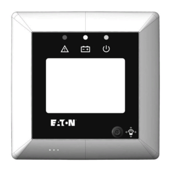
5 minutes after back light time off (see section 4.2.8 Lo- mote indicator for emergency lighting systems. gout) NOTE Only one Remote display can be connected to one SelvGuard. Figure 1 - Remote display SG48-RC-LCD-30 Remote display for SG48, 30° mount. base SG48-RC-LCD-55 Remote display for SG48, 55°... -
Page 4: Mounting Options
3 Mounting options 3 Mounting options The Remote display is supplied with a 30° or 55° inclined mounting base for different mounting options. Remote display 30° LEDs User viewing side LEDs LEDs Navigation switch User viewing side User viewing side Navigation switch Navigation switch wall back entry... - Page 5 3 Mounting options Run cable through designed bottom grommet. Figure 5 - installing concealed cable (left) or cable coming below (right) For wall mounting installation, the base shall be mounted with the grommet on the bottom side; for the desk mounting instal- lation, the base shall be mounted with the grommet top side like below figure.
-
Page 6: Operation
4 Operation 4 Operation LEDs status Status LEDs Status No failure Green On Emergency Mode Red On + Yellow On Green On + indication on LCD of Delay on mains return remaining time before normal operation Function/Duration Test Yellow On Luminaire is blocked All LEDs are off Charging failure... -
Page 7: All User Menu
4.1 All user menu 4.1 All user menu Main Menu Monitor Main menu is made up of 4 submenus: System Info Language - Monitor Login - System Info Back - Language - Login Monitor, System Info and Language menu is accessible for all personel. -
Page 8: Login
4.1.4 Login 4.1.4 Login This screen is used to select different access levels, e.g. Ad- Main menu min or User. At first start-up User is deactivated. User can be Monitor System Info activated / deactivated when logged in as Admin from 6.2 Ad- Language min main menu - Manage account. - Page 9 Admin Password: User ****** To recover password, firstly call/email your Eaton service cen- Back ter and provide your details together with the controller Serial Number. You'll find serial number on the System Info page, un- der SN. after you send this number to your service center, you...
-
Page 10: Admin Main Menu
4.2 Admin main menu 4.2 Admin main menu Main menu Monitor System info After Admin/User activation, additional menu features will be Test available in the menu: Faults and Events Config Parameters - Monitor Features - Test Display settings - Faults and Events - Config. -
Page 11: Block And Reset Alarm
4.2.2 Block and Reset Alarm 4.2.2 Block and Reset Alarm Main menu Monitor Test In this section Admin can manually activate from local display Faults and Events Inhibit and Rest Mode. When active, either can be released via Config Parameters Display settings Release Device. - Page 12 In this scenario, Load will be disconnected from Batt Open system. Please check both battery isolator and Battery Fuse and reach Eaton service for further assistance. If the battery charging current is greater than expected battery charging current Batt High Charging ...
-
Page 13: Config Parameters
Vtg to Turn Load • Factory Default • Manual Control • Change Password Battery NOTE: Only Eaton trained personel shall make changes to parameters within Battery menu. Wrong battery set-up can damage the batteries permanently and void system warranty. Back... - Page 14 Circuit Setup Circuit Setup Back Circuit Setup Use joy-stsick to access “Circuit Setup” menu where you Output 1 can select between maintained or non-maintained func- Maintained Maintained tionality for each individual End circuit group Output 2 Non Maintained Back (Output1 / Output2): Non Maintained Output1 (consisting by default of circuits 1 to 6) and Output2 (consisting by default of circuits 7 and 8).
- Page 15 Secure Input Secure Input Secure Input Use joy-stick to access “Secure Input” options where Secure Input 1 you can select “Secure Inputs” functionality. By default AC fail input AC fail input no function is selected for Secure Inputs. Usually, Secure Inhibit Trigger 1 Input1 (SI1) is used for key lock (inhibit or rest mode) and...
- Page 16 Relay Outputs Relay Outputs Relay Output Relay Relay Use joy-stick to access “Relay Outputs” menu where you Mains fault Relay Charge fault Relay can configure relay outputs functionality: CKT fault • Mains On Common Sys Fault * Deep Discharge ACK •...
- Page 17 Extended Emergency Extended Emergency In this section Admin can adjust Delay On Mains Return features: Manual / Automatic and Duration time. Delay On Mains Return represents the duration after non-maintained lights are turned off when mains returns. If 'Manual' is selected, then only Admin can turn-off non- maintained lights after mains return via local display (see section 4.2.2 Block and Reset Alarm) or via Optional Input (Manual Reset function).
- Page 18 Manual Control Manual Control If Admin is deactivated, on every power on or when switch to Home screen to Main Menu it will always enter into Admin Main Menu. Use joy-stick to access "Manual Control" where you can manually control the connected Load (Output1 and Manual Control Output2).
-
Page 19: Features
4.2.6 Features 4.2.6 Features Main menu Features Monitor Use joy-stick to access “Features” menu where you can System info Remote Panel TestTest enable or disable additional system features like: Faults and Events 1. BBM (Battery Block Monitoring) Config Parameters Features 2. -
Page 20: Manage Account
Config Parameters anyone with access to the LPS. Features System Info Language NOTE Manage Account Logout Eaton does not advise to disable password due to safety Back reasons. ATTENTION Disable password protection under your sole responsibility. Back Manage Account Password Protection... -
Page 21: Notes
Notes Notes CEAG Remote Display for Central Power Supply Systems 40071860348 October 2019 www.ceag.de... -
Page 22: General Safety Instructions - Devices
General Safety instructions - devices General Safety instructions - devices Deutsch English Hrvatski Allgemeine Sicherheitshinweise General safety instructions Opće sigurnosne upute • Die Geräte sind nicht für den privaten Gebrauch • The devices are not suitable for private use. • Uređaji nisu prikladni za privatnu upotrebu. geeignet. - Page 23 General Safety instructions - devices General Safety instructions - devices • Fjern alle fremmedlegemer fra enhetene før rezervă, tensiunea de reglare și curenții de Lietuviškas Suomalainen første gangs bruk. scurgere.) Nu întrerupeți circuitele sub sarcină. Bendrieji saugos nurodymai Yleiset turvallisuusohjeet •...
- Page 24 At Eaton, we’re energized by the challenge of powering a world that demands more. With over 100 years experience in electrical power management, we have the expertise to see beyond today. From groundbreaking products to turnkey design and engineering services, critical industries around the globe count on Eaton.