
Related Manuals for General CM660


Summary of Contents for General CM660
- Page 1 RUGGED AUTO RANGING TRUE RMS AC/DC CLAMP METERS USER’S MANUAL CM660: 0 TO 600A, MAX CM700: 0 TO 1000A, MAX Please read this manual carefully and thoroughly before using this product.
-
Page 2: Table Of Contents
Operating Instructions....11 – 24 General Instructions....11 – 14 Ranging Options . -
Page 3: Introduction
The only difference between the CM660 and CM700 involves their current measurement range and resolution. Where the CM660 has a 0 to 600A measurement range and a maximum current resolution of 0.01A, the CM700 has a 0 to 1000A measurement range and a maximum resolution of 0.1A. -
Page 4: What's In The Blister Pack
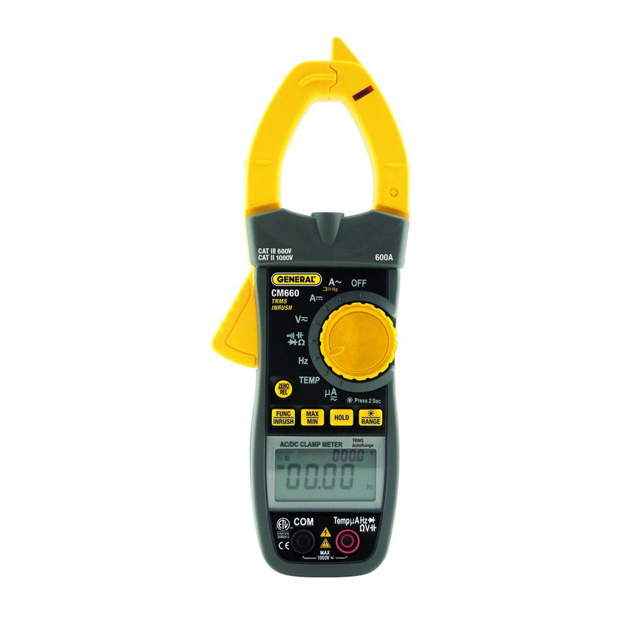
PRODUCT OVERVIEW Fig. 1 shows the labels and positions of the controls, indicators and physical structures of the CM660 and CM700. Fig. 2 shows all possible indications on the LCD of either unit. Familiarize yourself with the... - Page 5 Fig. 1. The controls, AUTO indicators and physical structures of the CM660 and CM700. 1. Non-contact voltage (NCV) sensor 2. NCV visual indicator 3. LED work light 4. Rotary function switch 5. Multi-function buttons: ZERO/REL—Used to 1) Reset DC current...
- Page 6 FUNC/INRUSH—1) Selects among resistance measurement, capacitance measurement, diode integrity and continuity check modes with rotary function switch in position, 2) Switches between AC and DC with rotary function switch in position, 3) Enters surge current measurement mode with rotary function in position, 4) Enters NCV sensitivity set mode if pressed and held when powering on the meter.
-
Page 7: Safety Instructions
AUTO Fig. 2. All possible display indications SAFETY INSTRUCTIONS •• •• Warning To avoid possible electric shock or personal injury, and to avoid damaging the meter or the equipment under test: • Do not use the meter in any way not detailed in this manual or the meter's safety features may be compromised. - Page 8 • •WARNING Do not measure voltages above 1000V in Category III installations. • •WARNING Do not measure voltage when the function switch points to the resistance (ohms), current, capacitance or temperature settings. Never measure current when the switch points to the resistance (ohms), capacitance or temperature settings.
- Page 9 • Use only three “AAA” batteries, properly installed in the battery compartment, to power the meter. Do not use rechargeable batteries. • Replace the batteries as soon as the low battery indicator “ ” appears. Operated with weak batteries, the meter might produce false readings that could lead to electric shock and personal injury.
-
Page 10: Setup Instructions
CAT IV level make arc flash possible. SETUP INSTRUCTIONS INSTALL BATTERIES The battery compartment of the CM660/700 is located at the back of the meter. To open the compartment, use a small Phillips-head screwdriver to remove the single screw securing the battery compartment cover. -
Page 11: Operating Instructions
OPERATING INSTRUCTIONS GENERAL INSTRUCTIONS The CM660/700 provides several functions that can be applied to measurements and displays of multiple parameters. Ranging Options. By default, the meter automatically chooses the measurement range that maximizes the resolution of its current, voltage, resistance, capacitance, frequency and temperature measurements. -
Page 12: Making Relative Measurements
readout to show the l rgest value of the parameter being measured since entering that measurement mode. The primary display and the analog bar graph below it will continue to show real-time readings. Pressing the MAX/MIN button a second time switches the secondary readout to show the sm llest value of the parameter being measured since entering that measurement mode. -
Page 13: Using The Analog Bar Graph
icon on the left side of the LCD indicates that the APO function is enabled. Once the APO function has activated and powered the meter off, you cannot reactivate the meter simply by turning the rotary function switch to a different position. -
Page 14: Measuring Ac Or Dc Current
To avoid having the backlight drain the meter’s batteries, the backlight (and work light, if activated) automatically extinguishes in 20 seconds. MEASURING AC OR DC CURRENT •• •• Warning Before making current measurements, make certain that all test leads are disconnected from the meter terminals. -
Page 15: Measuring Ac Inrush Current
LCD and the primary readout will show the motor’s surge current (to a maximum of 600A for the CM660 and 1000A for the CM700). For this application, the current is measured by the clamp jaw, after it has been placed around one conductor of the motor’s power supply line. -
Page 16: Measuring Ac Or Dc Voltage
To measure a microamp current: 1. Turn the rotary function switch to the A position. 2. Plug the red and black test leads into the red and black jacks at the bottom front of the meter. 3. Connect the test leads in series with the device whose current flow you wish to measure. - Page 17 Unlike other NCV detectors with only one sensitivity level—and therefore the ability to detect only one range of voltages (typically 50 to 600VAC)—the detector in the CM660 and CM700 has four sensitivity levels. They were chosen to optimize voltage detection over four practical ranges: 12 to 25VAC, 70 to 125VAC, 150 to 240VAC and 250 to 600VAC.
- Page 18 “hot” wire; any of the wires could be activating the alarms. The NCV detector in the CM660/700 can help you isolate the hot wire. This application calls for turning down the sensitivity in stages after the NCV detector senses voltage. As you...
- Page 19 •• •• Warning The NCV detector in the CM660/700 is designed to indicate the presence of AC voltage with an amplitude between 12VAC and 600VAC. Accordingly, do not assume that the absence of a positive indication means that the circuit under test is de-energized (not “hot”).
-
Page 20: Measuring Resistance
MEASURING RESISTANCE •• •• Warning To avoid electrical shock or damage to the meter when measuring resistance or continuity in a circuit, make sure power to the circuit is turned off and all capacitors are discharged. (1) Turn the rotary function switch to the position. -
Page 21: Checking The Integrity Of A Diode
(2) Plug the red and black test leads into the red and black jacks at the bottom front of the meter. (3) Touch or clip the test leads to any two points of a circuit. The resistance between those two points will be shown on the primary readout. -
Page 22: Measuring Capacitance
MEASURING CAPACITANCE •• •• Warning To avoid possible damage to the meter or other equipment, turn off the power source and discharge all high-voltage capacitors. (1) Disconnect the capacitor from power. (2) Short the capacitor’s terminals to discharge it. (3) Disconnect any resistors between the terminals of the capacitor. -
Page 23: Measuring Temperature
(4) Read the measured frequency on the primary readout and the duty cycle (as a percentage) on the secondary readout in the upper right corner of the LCD. With the rotary function switch in the Hz position, the meter can measure frequencies from 10Hz to 60MHz with an accuracy of ±(0.5% of the reading + 3 digits). -
Page 24: Specifications
(3) Plug the included “K” type thermocouple (or a different “K” type thermocouple) into the adapter. Make sure to insert the slightly wider blade of the thermocouple into the – (negative) slot of the adapter. SPECIFICATIONS Parameter or Feature/Function Specification AC voltage (True Measurement ranges Measurement accuracy... - Page 25 (including ambient air), make sure that the tip of the thermocouple is within the fluid. Read the measured temperature on the primary readout in degrees Fahrenheit and on the secondary readout in degrees Celsius. CM660 CM700 0 to 600mV/6V/60V/600V/1000V ±(0.8% of reading + 3 digits) 0 to 600mV/6V/60V/600V/1000V ±(0.5% of reading + 3 digits)
- Page 26 Frequency (in Hz mode) Measurement ranges Measurement accuracy Capacitance Measurement ranges Measurement accuracy Continuity Threshold Diode integrity Open circuit voltage Duty cycle Measurement range Measurement accuracy Temperature (via included Measurement range “K” type stem thermocouple) Measurement accuracy Overload protection level in resistance, continuity, diode integrity, capacitance and A modes Input impedance Sampling time...
- Page 27 10Hz to 60Hz/600Hz/6kHz/60kHz/600kHz/6MHz/60MHz for 3V peak-to-peak square wave ±(0.3% of reading + 5 digits) 0 to 6nF/60nF/600nF/6 F/60 F/600 F/6mF/60mF ±(5% of reading+ 5 digits)@<10nF; ±(4% of reading+ 5 digits)@>10nF 50Ω 2.8V 1 to 99% ±3% -58° to 1112°F (-50° to 600°C) ±(2% + 2 digits) 250VAC/DC 10MΩ...
-
Page 28: Operating & Maintenance Tips
To replace the battery, follow the instructions on p. 10. Do not operate the CM660/700 in the presence of flammable or explosive gas or near an arc welder or induction heater. -
Page 29: Warranty Information
Meter is warranted to the original purchaser to be free from defects in material and workmanship for a period of three years. Subject to certain restrictions, General will repair or replace this instrument if, after examination, the company determines it to be defective in material or workmanship. -
Page 30: Return For Repair Policy
Customer Service to obtain an RGA (Return Goods Authorization) number before forwarding the unit via prepaid freight to the attention of our Service Center at this address: General Tools & Instruments 75 Seaview Drive Secaucus, NJ 07094 212-431-6100 Remember to include a copy of your proof of purchase, your return address, and your phone number and/or e-mail address. - Page 31 NOTES ______________________________________ ______________________________________ ______________________________________ ______________________________________ ______________________________________ ______________________________________ ______________________________________ ______________________________________ ______________________________________ ______________________________________ ______________________________________ ______________________________________ ______________________________________ ______________________________________ ______________________________________ ______________________________________ ______________________________________ ______________________________________ ______________________________________ ______________________________________ ______________________________________...
- Page 32 General Tools & Instruments GeneralToolsNYC...
Need help?
Do you have a question about the CM660 and is the answer not in the manual?
Questions and answers