Table of Contents
Advertisement
Quick Links
Advertisement
Table of Contents

Related Manuals for Bernina Q 24


Summary of Contents for Bernina Q 24
- Page 1 BERNINA Q 24 | Q 20 Frame Mounting Manual...
- Page 3 Edition notice Text, Setting and Layout BERNINA International AG Photos Patrice Heilmann, Winterthur BERNINA International AG, Steckborn Order number 2019-04 en 0365655.10A.04 Copyright 2018 BERNINA International AG All rights reserved: For technical reasons and for the purpose of product improvements, changes concerning the features of the machine can be made at any time and without advance notice.
-
Page 4: Table Of Contents
Quilting frame disposal ........... 62 Rail support assembly ..........23 Specifications ............63 Attaching rail supports ..........Adapting the rail support for BERNINA Q 20 ....Appendix .............. 64 Tabletop positioning ..........25 Differing information for the "Large" quilting frame Attaching tabletop brackets ........ -
Page 5: Important Safety Instructions
IMPORTANT SAFETY INSTRUCTIONS Please observe the following general safety instructions when assembling the quilting frame. Before using the quilting frame, also read the operating instructions for the machine from the BERNINA Q Series carefully. WARNING To protect persons from injuries: •... - Page 6 Proper use The quilt frame serves as a support for the machines in the Q series and as a workplace for long arm quilting. Any other use is not considered proper. BERNINA assumes no liability for consequences resulting from improper use.
-
Page 7: My Bernina
Labels a hazard which can lead to material damage if not avoided. NOTICE Tips from BERNINA quilt experts can be found next to this symbol. Example images are used in these operating instructions for the purposes of illustration. The machines shown in the images and the accessories shown therefore do not always match the actual items included with your machine. -
Page 8: Overview Of The Quilting Frame
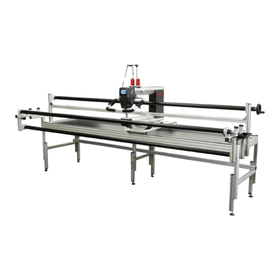
My BERNINA 1.3 Overview of the quilting frame Legs, left Cross bar, rear Tabletops Rail support, right Rail support, left Top rail Backing rail Cross bar, bottom Dead bar Legs, right Machine Track, front Take-up rail Legs, center Storage tray... -
Page 9: Overview Of Delivery
My BERNINA 1.4 Overview of delivery The machines in the BERNINA Q Series for quilting frames are delivered in three packages. Any special accessories ordered additionally will be supplied in separate packages. These accessories are not taken into account in these assembly instructions. -
Page 10: Overview Of Small Parts
My BERNINA 1.6 Overview of small parts All small parts such as screws, nuts, washers, etc. that are required for assembly of the standard quilting frame can be found in cardboard box 2. The parts are packaged in bags or boxes. We recommend unpacking all parts and then sorting them based on type. - Page 11 My BERNINA Figure Number Designation Code Tool Head cap screw, M5×16 Torx T25 screwdriver Carriage alignment Head cap screw, M6×50 Allen key no. 5 Attaching the front bar Button head self-tapping Torx T30 screwdriver Attaching the front track screw, 6.3×22 Slot nut, M6, comprising a Allen key no. 5...
- Page 12 My BERNINA Figure Number Designation Code Tool Serrated lock washer, M6 Carriage alignment Tab. 2: Overview of washers, nuts Figure Number Designation Code Tool Leveling foot Open-ended wrench no. 14 Attaching adjustable leveling feet Storage tray, black – Attaching the storage trays Handwheel, black, sticker/ Allen key no. 3...
- Page 13 My BERNINA Figure Number Designation Code Tool Self-adhesive felt strips, – Positioning tabletops black Cover cap for Y rails – Carriage alignment Cover cap for X rails – Carriage alignment Y safety bracket – Carriage alignment X safety bracket –...
-
Page 14: Quilting Frame Assembly
> Open the packaging and unpack the individual parts. > Check the individual parts for damage. > Check that the delivery is complete. > If parts are missing or if you have any questions about the assembly, contact your specialist BERNINA dealer immediately. 2.2 Recurring steps The following instructions describe steps that you need to perform repeatedly during assembly of the quilting frame. -
Page 15: Tightening The Socket Screws
Quilting frame assembly > Insert the screw through the borehole and screw it into the slot nut. > Tighten the screw, holding the Allen key by the long end. Tightening the socket screws > Always hold the Allen key by the long end when tightening the SN1, S1, S3, S4, S5, S8, and S11 screws. 2.3 Sequence of assembly steps 1. - Page 16 Quilting frame assembly CAUTION! Do not adjust the height of the quilting frame using the height-adjustable levelling feet. These are only intended for horizontal alignment of the quilting frame. Determining the optimal working height The optimal working height (b) is the height of the lower edge of your elbow when your arm is bent at right angles.
-
Page 17: Base Frame Assembly
Quilting frame assembly Required parts and tools: • Allen key no. 6 (T1) • Tape measure (not included in the scope of delivery) Prerequisite: • The optimal leg length is determined. > Undo the two locking screws on each leg. – The two leg segments can be moved against one another. >... -
Page 18: Attachting Adjustable Levelling Feet
Quilting frame assembly Attachting adjustable levelling feet The adjustable levelling feet are used to level the quilting frame (see page 26). To ensure sufficient scope for precision adjustment of the height, the levelling feet must not be screwed in as far as they can go. Required parts and tools: •... - Page 19 Quilting frame assembly > Lay out large parts in approximately the right position on the floor. > Place the lower cross bar onto the lower longitudinal bar of the central leg in such a way that the central borehole is located precisely above the pre-fitted slot nut. >...
-
Page 20: Attaching The Back Bar
Quilting frame assembly > Place a washer (W3) onto a head cap screw (S2). Tighten the screw. > Place the right-hand edge of the cross bar onto the lower longitudinal bar of the right leg in such a way that the borehole is located precisely above the pre-fitted slot nut. >... - Page 21 Quilting frame assembly Positioning the rear cross bar > Place the cross bar onto the central leg in such a way that the inserted slot nuts are located in the lower slot and point inward. The "TOP" sticker faces upward. >...
- Page 22 Quilting frame assembly > Insert the rear cross bar into the slot of the right leg in such a way that the upper edges of the rear cross bar and the right-hand longitudinal bar are at the same height. Attaching the rear cross bar to the right and left leg Carry out the following tasks on both sides.
-
Page 23: Attaching The Front Bar
Quilting frame assembly Attaching the rear cross bar to the central leg > Push the upper longitudinal bar on the central leg backward again so that it fits into the lower slot on the internal surface of the cross bar. >... - Page 24 Quilting frame assembly > Move the inserted slot nuts in such a way that there are the same number of slot nuts to the right and the left of the central leg. Attaching the front cross bar to the right and left leg Carry out the following tasks on both sides.
-
Page 25: Rail Support Assembly
Quilting frame assembly 2.6 Rail support assembly Attaching rail supports Required parts and tools: • Rail support, left • Rail support, right • 8× head cap screws M8×40 (S1) • 8× serrated washers M8 (W2) • Allen key no. 6 (T1) Carry out the following tasks on both sides. -
Page 26: Adapting The Rail Support For Bernina Q 20
Quilting frame assembly > Tighten the head cap screws (S1) (see page 13). Adapting the rail support for BERNINA Q 20 Required parts and tools: • Allen key no. 6 (T1) Carry out the following tasks on both sides. > Undo the two screws on the top of the rail support. -
Page 27: Tabletop Positioning
Quilting frame assembly 2.7 Tabletop positioning Attaching tabletop brackets Attach a total of eight metal brackets as supports for the tabletops, comprising four in the rear cross bar and four in the front cross bar. Required parts and tools: • 8× metal brackets (M10) •... -
Page 28: Quilting Frame Levelling
Quilting frame assembly > Position the metal brackets (M10) so that two tabletops rest on each bracket. Tighten the screws (see page 13). > Place the tabletops onto the metal brackets (M10) so that the tabletops are stable. > If necessary, carefully undo the metal brackets (M10) and reposition them. 2.8 Quilting frame levelling To allow the machine to move smoothly on the quilting frame, the quilting frame must be aligned perfectly horizontally using the levelling feet after assembly. -
Page 29: Track Assembly
Quilting frame assembly > Tighten the counternuts on all six legs. 2.9 Track assembly Attaching the rear track Required parts and tools: • 8x head cap screws M4×16 (S6) • 1× track • 2× black plastic inserts • Allen key no. 3 (T1) >... - Page 30 Quilting frame assembly > Push the two black plastic inserts back into the track. > Place the track onto the rear cross bar so that the screw holes (1) are precisely above the threads (2) of the pre-fitted rail and the flat part of the track is pointing inward. >...
-
Page 31: Attaching The Front Track
Quilting frame assembly > To ensure that the carriage later rests optimally on the tracks, pull the track outwards and then tighten all head cap screws (S6). Attaching the front track Required parts and tools: • 8× head cap screws M4×16 (S6) •... - Page 32 Quilting frame assembly > Push the two black plastic inserts back into the track. > Place the track onto the front cross bar so that the screw holes (1) are precisely above the threads (2) of the pre-fitted rail and the flat part of the track is pointing inward. >...
-
Page 33: Top And Backing Rail Assembly
Quilting frame assembly > To ensure that the carriage later rests optimally on the tracks, pull the track outwards and then tighten all head cap screws (S6). > Screw in one button head self-tapping screw (S12) on each of the two sides of the track. 2.10 Top and backing rail assembly The top rail and backing rail are fitted to the rail supports at the front. -
Page 34: Assembling The Top Rail
Quilting frame assembly Assembling the top rail Required parts and tools: • Top rail • Ratchet wheel (M7) • 2× head cap screws M8×50 (S4) • Allen key no. 2 and no. 6 (T1) > Push the ratchet wheel (M7) over the right-hand end of the top rail so that the teeth are pointing forward when viewed from the front of the quilting frame. -
Page 35: Assembling The Backing Rail
Quilting frame assembly > Tighten the pre-fitted grub screws so that the rail and ratchet wheel are securely connected to one another. Assembling the backing rail Required parts and tools: • Backing rail • 1× setting collar (M6) • 1× ratchet wheel (M7) •... - Page 36 Quilting frame assembly > Push the ratchet wheel (M7) over the right-hand end of the backing rail so that the teeth are pointing backward when viewed from the front of the quilting frame. > Push both ends of the backing rail into the upper rail brackets of the rail supports. >...
-
Page 37: Carriage And Park Position Magnet Alignment
Quilting frame assembly 2.11 Carriage and park position magnet alignment Positioning the carriage Required parts and tools: • Carriage > Position the carriage on the tracks so that the hole for the park position magnet (M8) is pointing to the left when viewed from the front. >... - Page 38 Quilting frame assembly > Undo the four screws to align the carriage. > Align the carriage so that it slides smoothly over the tracks along the entire length of the quilting frame and all wheels are in contact with the tracks at all times. >...
- Page 39 Quilting frame assembly > Press the black rubber cap (M9) over the magnet (M8). > Screw the head cap screw (S1) into the pre-mounted slot nut in the rear vertical profile of the left-hand rail support, but only tighten it slightly so that it can still be moved. >...
-
Page 40: Machine Preparation
• 4× V-wheel units (P16) (carriage accessories, cardboard box 2) • Allen key no. 5 (T1) • Torx screwdrivers (T20 and T25) (included in the box with the BERNINA Q Series machine) • Slotted screwdriver, medium-sized (not included in the scope of delivery) - Page 41 Quilting frame assembly Figure Numbe Designation Code Tool Head cap screw Torx T25 screwdriver Attaching the rear stand profile Head cap screw Allen key no. 5 (T1) Attaching the front stand profile Head cap screw Torx T20 screwdriver Attaching the rear stand profile Washer, thick, small Attaching the front stand...
- Page 42 Quilting frame assembly Overview of assembly Important notes on the stand profiles Both stand profiles have a round hole on one side and a slotted opening on the other side for attaching the V-wheels. The slotted opening allows the V-wheels to be subsequently aligned, so that they rest perfectly on the tracks of the carriage.
-
Page 43: Getting The Machine Ready
Quilting frame assembly Sequence of assembly steps 1. Getting the machine ready (see page 41) 2. Attaching the V-wheel units (see page 41) 3. Attaching the front stand profile (see page 42) 4. Attaching the rear stand profile (see page 44) 5. Positioning the machine on the carriage (see page 46) 6. -
Page 44: Attaching The Front Stand Profile
Quilting frame assembly > Position the V-wheel unit under the outer round hole, insert the screw from above and then tighten it. > On the other side of the profile, position the V-wheel unit (P16) below the slot so that the distance from the left-hand screw head to the right-hand screw head is approximately 28 cm (11 inches). - Page 45 Quilting frame assembly • Slotted screwdriver, medium-sized (not included in the scope of delivery) > Push the spring washer (P7) over the thread on the short threaded bolt (P6). > Screw the threaded bolt into one of the two smaller holes in the center of the front stand profile and tighten it using the slotted screwdriver.
-
Page 46: Attaching The Rear Stand Profile
Quilting frame assembly • Assembled stand profile • Allen key no. 5 (T1) Prerequisite: • The machine is on its side (see page 41). > Screw the screw (P11) into the thread on the front slot nut, but only tighten it slightly so that the profile can still be moved. - Page 47 Quilting frame assembly > Insert the two screws (P12) on the right and the left and tighten them using the Torx T20 screwdriver. > Push the screw (P10) with the washer (P9) through the central hole from below. > Align the stand profile so that the V-wheel unit which is fitted in the slotted hole is on the same side as with the front stand profile (top or bottom).
-
Page 48: Positioning The Machine On The Carriage
Quilting frame assembly Positioning the machine on the carriage Risk of injury from improper transport CAUTION Risk of injury and damage to the machine. > Position the machine on the carriage with the help of another person. > Leave the machine in the park position until the dead bar and take-up rail have been fitted. Required parts and tools: •... -
Page 49: Attaching Safety Brackets
Quilting frame assembly > Carefully push the machine up to the left-hand rail support and into the park position. Attaching safety brackets The machine is secured from tipping over with two types of safety brackets: • Y safety brackets secure the machine on the carriage and are fitted to the machine's stand profiles. •... - Page 50 Quilting frame assembly > Loosely tighten the hex nut (N2) from below, with the ribbed surface facing upward. > Push the Y safety bracket (M14) all the way up to the rail and then pull it approximately 1 mm back. –...
-
Page 51: Fitting Rail Covers
Quilting frame assembly Checking the position of the Y safety brackets > Move the machine forward and backward. > Check whether the Y safety brackets (M14) brush against the wheels. > If they do, pull the Y safety brackets approximately 1 mm away from the wheels. >... -
Page 52: Take-Up Rail And Dead Bar Attachment
Quilting frame assembly > Attach the rail covers to the ends of the rail pair brackets on the carriage, pressing them as far as they will go. 2.13 Take-up rail and dead bar attachment Attaching the Take-up rail Risk of injury from falling machine CAUTION Risk of injury and damage to the machine. - Page 53 Quilting frame assembly > Push the ratchet wheel (M7) over the right-hand end of the take-up rail so that the teeth of the ratchet wheel are pointing backward when viewed from the front of the quilting frame. > Guide the take-up rail through the neck of the machine. >...
-
Page 54: Attaching The Handwheel To The Take-Up Rail
Quilting frame assembly > Tighten the pre-fitted grub screws so that the rail and ratchet wheel are securely connected to one another. Attaching the handwheel to the take-up rail Required parts and tools: • Handwheel (M3) • Locking piece (M4) •... -
Page 55: Attaching The Dead Bar
Quilting frame assembly > Push the countersunk screw washer (W4) onto the countersunk screw (S3). > Insert the screw into the screw hole and tighten it carefully. > Cover the countersunk screw (S3) with a sticker. > Screw the winder bolt (M5) to the handwheel (M3). Attaching the dead bar Risk of injury from falling machine CAUTION... - Page 56 Quilting frame assembly • 2x countersunk screws M8x14 (S8) • Allen key no. 5 (T1) > Guide the dead bar through the neck of the machine with the rounded off side facing backward. > Carry out the following tasks on both sides. >...
-
Page 57: Leader, Side Clamp, And Storage Tray Attachment
Quilting frame assembly > Tighten the countersunk screw. > Remove Allen key no. 6 (T1). > Move the machine to the right-hand edge of the quilting frame. > Repeat the test and height adjustment process. 2.14 Leader, side clamp, and storage tray attachment General notes on attaching the leaders •... -
Page 58: Attaching The Take-Up Leader
Quilting frame assembly > Determine the center of the backing rail using the tape measure and mark this position with a pencil. > Measure and then use a pencil to mark out a point 155 cm (61 inches) to the left and the right of the marked center. -
Page 59: Attaching The Top Leader
Quilting frame assembly > To mark the center of the take-up rail, unroll the back leader. Using a quilting guide, first transfer the center of the back leader onto the dead bar and from there onto the take-up rail. Make sure that everything is aligned correctly at right angles. -
Page 60: Attaching The Side Clamps
Quilting frame assembly > Transfer the center position of the unrolled back leader onto the top rail. > To make it easier to fit the top leader, swing the top rail upward. > Measure and then use a pencil to mark out a point 155 cm (61 inches) to the left and the right of the marked center. -
Page 61: Attaching The Storage Trays
Quilting frame assembly > Fix the bungee cord (M16) in the bracket. > Fit the remaining side clamps in the same way. Attaching the storage trays Required parts and tools: • 2× storage trays (M2) • 4× button head screws M5x12 (S7) •... -
Page 62: Front Handle Attachment
Quilting frame assembly 2.15 Front handle attachment Attaching the front handle unit > Screw the handle unit behind the head of the machine with the two screws from below so that the locking levers point backward. > Insert the cable of the handle unit into the connection at the back on the head of the machine. Adjusting the width of the handles NOTICE! To ensure that the thread does not get caught up on the locking lever when winding, always adjust the locking levers so that they point vertically downward when clamped. -
Page 63: Adjusting The Handles
Quilting frame assembly > Swing the locking lever down. – The handle is now fixed and the locking lever is pointing downward. Adjusting the handles > To adjust the handles, swing up the locking lever on both sides. > To adjust the length of the handle, pull the handle out of the bracket or push it into the bracket. >... -
Page 64: Disposal
Disposal 3.1 Quilting frame disposal BERNINA International AG is committed to environmental protection. We make every effort to increase the environmental friendliness of our products by continually improving their design and production technology. If you no longer require your quilting frame, please clean it, sort the components according to material and then dispose of these in line with local regulations and legislation. -
Page 65: Specifications
Specifications Specifications Dimensions of the quilting frame "Classic" quilting frame "Large" quilting frame "Small" quilting frame Length (A) 12' (3.60 m) 13' (4 m) 9' (2.75 m) Width (B) 3.9' (1.20 m) 3.9' (1.20 m) 3.9' (1.20 m) Height (C) 5.6' (1.70 m) 5.6' (1.70 m) 5.6' (1.70 m) -
Page 66: Appendix
Appendix Appendix 5.1 Differing information for the "Large" quilting frame Overview of large parts (see page 7) 5x tabletops: 3× large, 2× small Overview of small parts (see page 8) • 12x metal brackets (M10) • 16x felt strips (M11) • 12x countersunk screws M8x14 (S8) Attaching tabletop brackets (see page 25) >... - Page 67 Appendix Just two head cap screws M8 × 50 (S2) Just two washers M8 (W3) Do not perform any steps in the instructions that affect the central leg. Attaching the rear cross bar (see page 18) • Just four 4× slot nuts (SN1) are required •...
-
Page 68: Index
Index Index Adjusting the handles 61 Levelling feet attachment 16 Adjusting the working height 13 Levelling the quilting frame 26 Assembling the base frame 15 Assembling the machine 38 Machine Attaching side clamps 58 Attaching V-wheel units 41 Positioning on the carriage 46 Backing rail Safety brackets... - Page 69 Index Tabletops Attaching brackets 25 Positioning 25 Take-up rail Attaching 50 Attaching handwheel 52 Attaching the leaders 56 Top rail Attaching 32 Attaching the leaders 57 Unpacking the delivery 12...
Need help?
Do you have a question about the Q 24 and is the answer not in the manual?
Questions and answers