Table of Contents
Advertisement
Available languages
Available languages
Quick Links
MANTECATORI ORIZZONTALI ELETTRONICI
ELECTRONIC HORIZONTAL BATCH FREEZER
MANUALE D'USO
E
MANUTENZIONE
OPERATING INSTRUCTION
AND MAINTENANCE
Serie-Series-Serie-Serie
C119 06
C122 03
X f l y
l o
d F '«iKKw»«»'
r
cream machines
^
,ce
n
r
l-ris
I
''P - I
w
I
t
Azienda Certificata
UNI EN ISO 9001:2000
Numero Certifrcato
50 100 5650
Advertisement
Table of Contents

Related Manuals for Frigomat TAYLOR C122


Summary of Contents for Frigomat TAYLOR C122
- Page 1 MANTECATORI ORIZZONTALI ELETTRONICI ELECTRONIC HORIZONTAL BATCH FREEZER MANUALE D’USO MANUTENZIONE l-ris OPERATING INSTRUCTION AND MAINTENANCE Serie-Series-Serie-Serie C119 06 C122 03 ‘‘P - I Azienda Certificata UNI EN ISO 9001:2000 d F ’«iKKw»«»’ X f l y Numero Certifrcato 50 100 5650 cream machines...
- Page 2 S ^f/N G om m r • T W L O R e r a n a tiM C h in B B ■ » ■ IM P O R T A N T E Vi raccomandiamo di leggere attentamente e interamente questo manuale prima di utilizzare la Vostra macchina.
- Page 3 La macchina e coperta da garanzia secondo le condizioni illustrate sulla “CARTOLINA DI GARANZIA “ a corredo che deve essere debitamente compilata e restituita a: FRIGOMAT s.r.l., via 1° Maggio, 28 26862 GUARDAMIGLIO (LODI) - ITALIA Perfavore scrivete nel campo sottostante il numero di matricola della Vostra macchina...
-
Page 4: Table Of Contents
S ^ ffiK io m a T l " D S y L O R ‘®y INDICE 1. TRASPORTO, MOVIMENTAZIONE E IMMAGAZZINAMENTO ..Ispezione preliminare ............Dimensioni e pesi delle macchine imballate ..... Indicazioni per la messa fuori servizio ..... 2. -
Page 5: Trasporto, Movimentazione E Immagazzinamento
ITW LO R '® y ^^fKGomar ■ ■ " /C(l «W C /j/nu i! 1 TRASPORTO, MOVIMENTAZIONE E IMMAGAZZINAMENTO. 1.1 ISPEZIONE PRELIMINARE E IMMAGAZZINAMENTO La macchina viaggia a rischio e pericolo del committente, se notate danneggiamenti airimballaggio, fate immediatamente eccezione al vettore. Fate ugualmente eccezione al vettore subito dope I’apertura dell’inriballo, anche se do avviene qualche giorno dopo la consegna, se riscontrate qualche danneggiamento alia macchina. -
Page 6: Marcatura E Segni Grafici
ITAYLOR S ’f 's s s s MARCATURA E SEGNI GRAFICI La macchina e dotata di una targa e alcuni pittogrammi la cui conoscenza, unitamente al presente manuale, garantisce un utilizzo piu sicuro. Targa dati macchina r R i C O f T t t t T ' ' *<... - Page 7 (S^^ffUGomuT i T i i f l y L O R ‘®y Attenzione! A lta te n s io n e p r e s e n te a ll’in te rn o , p e ric o lo fo lg o ra z io n e . La seguente targhetta viene applicata sul coperchio del box elettrico ed avverte I’operatore che non deve in nessun caso rimuoverlo evitando cosi il pericolo di...
-
Page 8: Norme Generali Dl Sicurezza
S ^fR iG o m a r i T i f i Y L O R * ® v a e n m ri M c i ^ tn a s ■ 3. NORME GENERALI Dl SICUREZZA p e r i c d l o Rispettare rigorosamente le norme general! di sicurezza e prevenzione infortuni di seguito elencate: L’uso della macchina e consentito solo a personale in buono stato di salute,... -
Page 9: Installazione
(S ^fR K o m itr s T A Y L O R " ® y ▼ fc o Crnnm m a c h in e s ■ ■ 4. INSTALLAZIONE 4.1 IMPIEGHI Apparecchio idoneo alia mantecazione delle miscele per gelato e alia produzione di granita, secondo gli usi consentiti nei termini di Legge. -
Page 10: Messa In Funzione
j T 7 S Y L 0 R ' » y tito fin ^ in a c h in s s ■ *■ jjjg 4.5 MESSA IN FUNZIONE VVERTENZ TAYLOR declina ogni e qualsiasi responsabilita per i danni causati dalla mancata osservanza delle seguenti indicazioni. - Page 11 n i W L O R > (T^Fm aom oT If needed, carry out an equipotential bonding, using the screw placed on the rear of the machine below the frame and marked with the symbol shown to the left. Make sure that the cold water supply line intended for condensation has pressure values between 1 and 3 BAR and temperature between 13*"...
- Page 12 iW L O R ^ ^ rP .’ lOfuMT Condensation pressure (water models only). With the machine in production mode, after a few seconds condensation water must come out of the drain pipe at a temperature of about 35°C. if this is not the case, the pressure switch valve shown in the figure must be adjusted.
-
Page 13: Dispositivi Dl Sicurezza
ITifiy LOR » v (§ yfR iG o m a r ■ ■ * * ■ IcM crtm m n m tJtin n a 5. DISPOSITIVI Dl SICUREZZA Sicurezza anticesoiamento: Realizzata mediante circuito di sicurezza conforme alia direttiva europea; interviene all’apertura del portello e/o al sollevamento della griglia di sicurezza sulla tramoggia, commutando temporaneamente la macchina in STOP. -
Page 14: Funzionamento
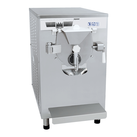
ITflYLOR S ^ FR K o m ttr 6. FUNZIONAMENTO 6.1 MACCHINA 1. Portello Chiude ermeticamente il cilindro durante le fasi di lavorazione. Puo essere facilmente rimosso per permetterne la pulizia. 2. Griglia di sicurezza - coperchio tramoggia Permette all’operatore di effettuare la carica del prodotto in tutta sicurezza. -
Page 15: Comandi
ITflYLOR » y S^fM G onuiT ■ * ■ tea CfanmmnchhMSi 6.2 COMANDI □ Q □ DISPLAY u U o Visualizza le informazioni relative ai programmi di lavoro e alle regolazioni consentite. II led si accende per segnalare I’apertura del portello, il sollevamento della griglia di sicurezza o eventuali anomalie airimpianto. - Page 16 S ^ffa G o m a r j “ | y S Y L O R ' ® y tr.a C f(* t\fn i n A e /u n B S ■ *■ ■ m » Con macchina in cicio automatico Hard, premendo nuovamente il tasto PRODUZIONE e possibile accedere al cicio semiautomatico con controllo di consistenza, che consente all’operatore di selezionare manualmente il livello di consistenza che si vuole...
-
Page 17: Produzione Gelato E Granita
I l i f i y L O R V ^ f f l / G O / n / i r e/rtfim nisc/jm a* ■ 6.3 PRODUZIONE Dl GELATO E GRANITA Dopo aver provveduto all’installazione della macchina conformemente alle istruzioni del capitold 3 ed averla accuratamente lavata e sanitizzata, secondo le istruzioni contenute nel capitolo 7, procedere nel modo seguente per iniziare la produzione di gelato: - Verificare che il rubinetto a saracinesca per... -
Page 18: Cicio Automatico
(S ^ fitK o m a r n y S Y L O R * ® y i c a c tm m tn e i C .h i n a % • 6.3.1 CICLO AUTOMATICO Premere il tasto PRODUZIONE per iniziare il cicio automatico di mantecazione. -
Page 19: Cicio Automatico Hard
I TiflY LOR 6.3.2 CiC L0 AUTOMATICO HARD- (X^ FRiGom /iT • ■ w - T ir.o a a u m tu n c h u tH it Premere il tasto PRODUZIONE per iniziare il cicio automatico di mantecazione, come descritto nel paragrafo precedente. -
Page 20: Cicio Semiautomatico Con Controllo Consistenza
I'TO/LOR S^fR K iom iiT 6.3.3 CICLO SEMIAUTOMATICO CON CONTROLLO Dl CONSISTENZA (solo utenti esperti) Premere il tasto PRODUZIONE, come descritto nei paragrafi precedenti. Sul display e visualizzata per alcuni istanti la sigla AUT o HRD a conferma dell’avvenuta selezione del cicio automatico o automatico HARD. - Page 21 cpeR fG om nT 5 T f l Y L O R * ® y ■ ■% • ' V - ▼ h:a r..'oam »w ch!nos In qualsiasi momento, e possibile passare alia fase d’estrazione del prodotto. - j ^ ^ S U G G E R I M E N T D ^ ^ - fine correggere eventual! errori...
-
Page 22: Cicio Semiautomatico Con Controllo Tempo
ITiOYLOR cp F R K o m a r 6.3.4 CICLO SEMIAUTOMATICO CON CONTROLLO DEL TEMPO (solo utenti esperti) Premere il tasto CICLO SEMIAUTOMATICO A TEMPO per selezionare il cicio semiautomatico di mantecazione con controllo del tempo (fig.1). I led dei tasti Conferma e DOWN accendono e sul display e visualizzato il set di tempo, espresso in minuti e compreso fra 0’... - Page 23 (S^FRIGOmOT i T W L O R ’®y • ■ " hui c ro w n m p c h h w i a t t e n z id n e fine correggere eventuali ''e rro ri programmazione iniziali, durante' I’esecuzione del cicio semiautomatico e sempre possibile variare il set di tempo impostato tramite la seguente prqcedura: Con cicio in atto, prerhere nuovamente il tasto...
-
Page 24: Programme Granita
ififlYLOR (jp F R K o m itT te a tm a rn m itth rm a ■ *■ ■ m 6.3.5 PROGRAMMA GRANITA CON CONTROLLO Dl CONSISTENZA Premere il tasto GRANITA (fig.1). led del tasti Conferma DOWN accendono e sul display e visualizzata la sigla GR1, che caratterizza il programma di produzione granita con controllo di consistenza e agitazione continua (fig. - Page 25 S ^fitiG o iim iT ^ T i f l Y L O R V k in a ra itm m arM s ■ . L / . < U / ■^SUGGERIMENTD^(% fine correggere- eventual! error! programmazione !n!z!al!, durante I’esecuzione del cicio GR1 e sempre posslBlIe varlare j F set d! consistenza ' Impostato tramite...
-
Page 26: Programme Granita Al C A Ffe
ifTSYLOR^y (S^fMGomar 6.3.6 PROGRAMMA GRANITA AL CAFFE’ - Premere il tasto GRANITA (fig.1). - I led del tasti UP, Conferma e DOWN si accendono e sul display e visualizzata la sigla GR1 (fig. 2). - Premere il tasto UP per visualizzare sul display la sigla GR2, che caratterizza il programma di... - Page 27 5TflYLO R ‘® y ■ ■ " * ■ ▼ Ian cfo n m m o ch h o a - ^ ^ S U G G E R I M E N T D - 5 ^ - fine correggere eventual! errori programmazione iniziali, durante I’esecuzione del...
-
Page 28: Estrazione
ITifiy LOR S ^ f/ttG o m iir K O e ta n n in M c iiin fift ■ 6.4 ESTRAZIONE Per estrarre il prodotto al termine di un cicio produttivo, fare riferimento alle seguenti istruzioni: - Posizionare sulla mensola frontale della macchina vaschetta fredda pulita... -
Page 29: Manutenzione
I w U D R ^ v ^F R H x> m m ‘ 7. MAINTENANCE 7.1 ROUTINE MAINTENANCE (INTENDED FOR USER) TTENTIDN A The fats present in the ice cream mixtures are ideal fields for the proliferation of bacterial loads and mould. - Page 30 :TflYLOR"®y orV/w(so/nar- Pour the maximum admitted load of cold drinking water into the machine to rinse the surfaces which were just treated with the sanitiser. Drain the rinse water and turn the machine off. When pre-washing is over, all the removable parts in contact with the product must be disassembled and sanitised in a separate tub.
- Page 31 iW L O R * B y (y^fR iG om /ir 9. Remove steel lever that controls dispenser disk from the central door pin. 10. Remove the spring. 11. Remove the dispenser disk. 12. Use the OR disassembly device to remove the 2 OR gaskets from their place.
- Page 32 iW LOR B y ^ P p fu c p n w r- REMOVING AND CLEANING STIRRER Pull the beater towards you to remove it from the batch freezing cylinder. Recover the seal gasket placed on the back of the beater.
- Page 33 ^TiW LO R ® y S^fKKiom ar " ■ ■ • ■ # ro c^o/m i ;H flc/j/n .» ji RISCIACQUO E ASCIUGATURA Lavarsi bene le mani e/o utilizzare guanti monouso in lattice. Estrarre dalla vasca di sanificazione tutti i componenti precedentemente smontati, scovolinati e immersi.
-
Page 34: Manutenzione Straordinaria
TO/LOR'»y appftiG om m te a tta n iu trjtO ' . itiK H *■ ■ ■■ ■ ^ MANUTENZIONE STRAORDINARIA (RIVOLTO AL PERSONALE QUALIFICATO) C A U T E L A Queste operazioni devono essere eseguite solo ed esclusivamente da personale qualificato autorizzato. - Page 35 5T 7S Y LO R "® y (S ^ fR iG o m u r ■ ■ " • ■ /firt <yea,ii TA B E LL A P R O G R A M M A Z IO N E S C H E D A “MEB^” (**) STEP DESCRIZIONE C l 22...
- Page 36 TiOY LOR S^ FRiG om oT tc R c jM in n ^ tc h in tiS TA B E LLA P R O G R A M M A Z IO N E S C H E D A “MEB^” (**) - continua - DESCRIZIONE STEP C122...
-
Page 37: Istruzioni Per L'identificazione Dei Guasti
n W L O R * » y S ^ f R t G o m a t \c o iiT tfa m m a c M n a s 8. ISTRUZIONI PER L’IDENTIFICAZIONE DEI GUASTI 8.1 GESTIONE DEGLI ALLARMI AMESSAGG\0^^ . -
Page 38: Ricerca Dei Guasti
n y v / L O R 8.2 RICERCA DEI GUASTI RIMED! PROBABILI CAUSE INCONVENIENTE Chiudere I’interruttore Interruttore generate aperto La macchina non parte Chiamare il tecnico Anomalia elettrica (pulsante STOP spento) Chiamare il tecnico Fusibili bruciati Pulire il condensatore con una spazzola, verificare il Macchine ad aria: condensatore ad funzionamento del motoventilatore... - Page 39 s T X ^ L O R S ^ fftiG o m /fT • V - .T h it a e im m a c h h o a ITALIANO - 38...
- Page 40 i" n flY L O R * ® y (T ^ fR iG o m ftr ■ fc o C/BV)lir/7J>9C/fl«OS IMPORTANT We recommend that you read this manual fully and carefully before using your appliance. It is in your interest to pay special attention to the warnings marked as follows: d a n g e r Failure to comply with this signal causes very serious risks for health, death, and medium and long term permanent damage.
- Page 41 The machine is,covered by warranty according to the terms illustrated in the "WARRANTY CARD" supplied. It must be properly filled in and returned to: FRIGOMAT s.r.l., via 1 ® Maggio, 28 26862 GUARDAMIGLIO (LODI) - ITALY Please write the serial number of your machine in the field below.
- Page 42 INDEX 1. TRANSPORTATION, HANDLING AND STORAGE..Preliminary inspection ........Dimensions and weights of packaged machines. Indications for decommissioning ......2. MARKING AND GRAPHIC SIGNS ........3. GENERAL SAFETY STANDARDS ........4. INSTALLATION ............4.1 Use • ..........4.2 Working limits ........
- Page 43 ITOYLOR*®v S ^ f/tiG o m /ir • ■ V.-<T f/o a m n'aehinn< 1 TRANSPORTATION, HANDLING AND STORAGE. 1.1 PRELIMINARY INSPECTION AND STORAGE The machine is transported at the risk and peril of the customer. If you notice any damage to the packaging, immediately inform the carrier.
- Page 44 n y S Y L O R " ® v S ^ F /t K o m ^ r • rim r J u tw s 2. MARKING AND GRAPHIC SIGNS The machine is provided with an identification plate and some pictograms. They must be known along with the manual to guarantee safe use.
- Page 45 n i f l J / L O R S ^ f n i d o m a r tu o o m m n e h ii M S ■ ■ m Attention! H ig h v o lta g e in s id e ; d a n g e r o f e le c tro c u tio n . This plate is applied on the cover of the electrical box and warns the operator that it must not be removed for any reason whatsoever, thus avoiding the danger...
- Page 46 ITAYLOR 3. GENERAL SAFETY STANDARDS d a n g e r Strictly observe the general safety and accident-prevention standards listed hereafter; Use of the machine is reserved for personnel in good health, responsible and appropriately trained as to allowed use and risks present. Use of the machine is reserved for operators who have read, understood and taken in all that is included in this manual.
- Page 47 ^ T f l Y L O R »y S ^ F m c o m s T 4. INSTALLATION 4.1 USE Appliance suitable for batch freezing of ice cream mixtures and slush production, according to use allowed by Law. 4.2 WORKING LIMITS Do not use the machine with inconstant power supplies or +/- 10% beyond the value indicated on the plate or with the power cable damaged;...
- Page 48 n 7 S Y L O R " » y S ^ F H iG o m iiT 4.5 ACTIVATION w a r n i n g TAYLOR declines all and any liability for damage caused by failure to comply with the following indications.
- Page 49 IW UDR " s y If needed, carry out an equipotential bonding, using the screw placed on the rear of the machine below the frame and marked with the symbol shown to the left. Make sure that the cold water supply line intended for condensation has pressure values between 1 and 3 BAR and temperature between 13°...
- Page 50 iT / C / L O R " » y Condensation pressure (water models only). With the machine in production mode, after a few seconds condensation water must come out of the drain pipe at a temperature of about 35®C. If this is not the case, the pressure switch valve shown in the figure must be adjusted.
- Page 51 IW UDR " » y (X^FRIGO/n/IT 5. SAFETY DEVICES Shearing-prevention safety device: Implemented by means of a safety circuit compliant with the European directive, it intervenes when the door is opened and/or when the safety grid on the hopper is lifted, temporarily switching the machine to STOP mode. Beater m otor overheating safety device: Implemented by means of a thermal relay;...
- Page 52 ^ = T A Y L O R > 6. OPERATION 6.1 MACHINE 1. Door Closes cylinder hermetically during processing phases. It can be easily removed for cleaning. 2. Safety grid - hopper cover Allows the operator to load the product safely. The cover keeps the mixture from coming into contact with dust.
- Page 53 iflYLOR“ ® y (S^ fM G om ar ■ ■ * * ■ w « * tta u m m a c h in e 6.2 CONTROLS O O P DISPLAY Displays the information relative to work programs and allowed adjustments.
- Page 54 ITAYLOR SEMI-AUTOMATIC CYCLE with consistency control. With the machine in automatic Hard cycle, by pressing the PRODUCTION key again it is possible to access the semi automatic cycle with consistency control that enables the operator to manually select the level of consistency one wishes to achieve. During programming, pressing the PRODUCTION/CONFIRM key confirms the selection of the menu entry or the value of the selected parameter.
- Page 55 ITifiYLOR ® v S^FRiGomar ■ ten rianm njac/7*nfl.» 6.3 ICE CREAM AND SLUSH PRODUCTION After having installed the machine in compliance with the instructions of chapter 3 and having accurately washed and sanitised it, according to the instructions contained in chapter 7, proceed as follows to start ice cream making: - Make sure that the gate valve of cold water for condensation is open (water models...
- Page 56 |" n flY L O R * ® y ( ^ F R iG o m iir ■ » ■ ■ ic a e tfie n t n t a c im » n 6.3.1 AUTOMATIC CYCLE Press PRODUCTION start automatic batch freezing cycle.
- Page 57 j1 ifly L O R * ® V (y?F /tK !O m iiT ir.o emsiiifuacJUnos ■ V - .T 6.3.2 AUTOMATIC HARD CYCLE Press the PRODUCTION key to start the automatic batch freezing cycle, as described in the previous section. The AUT message is viewed on the display for a few seconds to confirm the automatic cycle has been selected...
- Page 58 n 7 S Y L O R *® y S ^ m a o n m te n e iB m n n u rJ \m e ^ ■ ■ m -w.* 6.3.3 SEMI-AUTOMATIC CYCLE WITH CONSISTENCY CONTROL (only for experts) Press the PRODUCTION key, as described in the previous sections.
- Page 59 niWLOR*®y - j ^ ^ S U G G E S T I D N ^ ^ - In order to correct any initial programming errors, during the execution of the semi-automatic cycle it is always possible to vary the consistency setting via the following procedure: - With cycle...
- Page 60 I T flY L O R * ® y (jp fR iG o m a T " c ip :m ■ ■ • ■ /cft /n .jc/U ftflJi 6.3.4 SEMI-AUTOMATIC CYCLE WITH TIME CONTROL (only for experts) Press the SEMI-AUTOMATIC TIME CYCLE key to select the semi-automatic batch freezing cycle with time control (fig.
- Page 61 n i W L O R S ^ e m a d m a r ■ ' " " • • " ■ » v , - * /go cfa n n i ftuir.M nos In order to correct any initial programming errors, during the execution of the semi-autornatic cycle'it is always possible to vary th e ’...
- Page 62 ITflYLOR S ^ fn K o m a r ■ * ■ V - -T f.,anm tjMChmvs 6.3.5 SLUSH PROGRAM WITH CONSISTENCY CONTROL Press the SLUSH key (fig. 1). The LEDs of the UP, Confirm and DOWN keys light up and the GR1 message is viewed on the display, which distinguishes the slush production program with consistency control and continuous mixing (fig.
- Page 63 ITW ?LO R ® v C p f n i G o m r ^ ^ - S U G G E S f l d N $ i ^ In order to correct any initial progrartiming errors, during the execution of the 'G R I cycle'itMs always possible to vary the consistency •...
- Page 64 T f lY L O R * ® y S ^ f R iG o m a r ’ tea e tf^a m n u iC h in ^ TTENTIDN A 6.3.6 COFFEE SLUSH PROGRAM - Press the SLUSH key (fig.1). - The LEDs of the UP, Confirm and DOWN keys light up and the GR1 message (fig.
- Page 65 n y s y L O R '» y S ^ P n iG o m u r " ▼ k f t Cfdom nm chiiuui , , r- « r- r .- r . r-i ... v U / - ^ l S U G G E S T I D N - 5 ( ^ ^ In order to correct any initial programming errors, during the-execution of..the GR2 cycle it*’...
- Page 66 il] f l Y L O R * » y (T ^ fH iG o m /ir • cfpam «!flrHnss 6.4 EXTRACTION To extract the product at the end of a productive cycle, refer to the following instructions: - Position cold and clean tub of adequate capacity on the front shelf of the machine.
- Page 67 I T i f l Y L O R ® y a P ftiiG o m iiT * ■ ien nffsattunnehinaf! 7. MAINTENANCE 7.1 ROUTINE MAINTENANCE (INTENDED FOR USER) a t t e n t i d n The fats present in the ice cream mixtures are ideal fields for the proliferation of bacterial loads and mould.
- Page 68 ITOYLOR ap fiu G o m iiT Pour the maximum admitted load of cold drinking water into the machine to rinse the surfaces which were just treated with the sanitiser. Drain the rinse water and turn the machine off. When pre-washing is over, all the removable parts in contact with the product must be disassembled and sanitised in a separate tub.
- Page 69 iTA/LOR 9. Remove steel lever that controls dispenser disk from the central door pin. 10. Remove the spring. 11. Remove the dispenser disk. 12. Use the OR disassembly device to remove the 2 OR gaskets from their place. Immerse the previously disassembled components into the tub with the sanitising solution and brush the surfaces with care.
- Page 70 I T i O y L O R ^ ^ fR IG O m U T ■ ■ icAt c u ^ a itt iM C h in Q s REMOVING AND CLEANING STIRRER Pull the beater towards you to remove it from the batch freezing cylinder.
- Page 71 o P fR iG o itu iT RINSING AND DRYING Wash your hands well and/or wear disposable latex gloves. Remove from the sanitising tank all the components which were previously disassembled, brushed and immersed. Rinse them with plenty of cold drinking water, making sure to remove all possible leftover sanitising solution.
- Page 72 iT7iYLOR"®y S^fRKonutr ■ ■ - w * ctam n nuichlnns EXTRAORDINARY MAINTENANCE (INTENDED FOR QUALIFIED PERSONNEL) / ^ C A U T I D N / \ These operations are reserved exclusively for authorised qualified personnel. TAYLOR S.r.l. will not be held liable for damage to objects or harm to persons which occur due to failure to comply with the above.
- Page 73 I T O Y L O R ^ y (S ^ F R K io m a r "MEB^" (**) B O A R D P R O G R A M M IN G TA B LE STEP DESCRIPTION C122 C119 C119=5...
- Page 74 I T f lY L O R * » y (^ F M & D tn o T "MEB^" (**) B O A R D P R O G R A M M IN G TA B LE - continue - DESCRIPTION STEP C122...
- Page 75 A z ie n d a C e r t if lc a t a " ^ U N I E N IS O 9 0 0 1 :2 0 0 0 ? F R ia o _ _ _ N u m e r o C e r t if ic a t o macchine per gelato , 5 U U...
- Page 76 A z ie n d a C o r t if ic a t a r-n"iv/i U N I E N 1 8 0 9 0 0 1 :2 0 0 0 ^ F R i a o m N u m e r o C e r t if ic a t o macchinepergelato 5 0 1 0 0 5 6 5 0 BEDIENER-/BENUTZERHINWEIS...
- Page 77 I T i f l Y l O R '® y (jp fR iG o m m • fco e rtffl/7 1 m i7chin«« 8. INSTRUCTIONS FOR TROUBLESHOOTING 8.1 MANAGEMENT OF ALARMS D E S C R IP T IO N * ’.
- Page 78 n i W L O R a P f/U G o m m 8.2 TROUBLESHOOTING REMEDIES PROBABLE CAUSES PROBLEM Close the switch Master switch open The machine does not start Contact the technician Electrical anomaly (STOP button off) Contact the technician Fuses blown Clean the condenser with a brush, check functioning of the fan and...
- Page 79 i X f l Y L O R »y S p F R K io m fiT 9 APPENDICI / APPENDICES / ANNEXES / ANHANG / APENDICES 9.1 Dati tecnici / Machine specifications / Caracteristiques techniques / Technische Daten / Datos Tecnicos *Larghe Profonditb Peso...
- Page 80 i TOY LOR * ® v cPfRiGomitr te n a e a m m a tb ln a x • ■ • • ■ Schema circuito frigorifero / Refrigerant circuit diagram / Schema du circuit frigorifique / Kuhinetzplan / Esquema circuito frigorifico. 9.2.1 C119 .....
- Page 81 |"TiflY L O R *® y (X^fRKomur 9.2.2 C122 r ^ E v ....Valvola pressostatica Filtro Condensatore ad acqua Elettrovalvola gas Water valve Filter Water condensator Gas electo valve Soupape pressostatique Condensation ^ eau Vanne ^l^ctrlque gas Filtre Druckventil Filter Wasserkondenslerung...
- Page 82 Spem aom ar ■ ■ M fl c r e a m m n th in o y 9.3 IMPIANTO ELETTRICO / ELECTRIC SYSTEM / GROUPE ELECTRIQUE / ELEKTRISCHE ANLAGE / INSTALACION ELECTRICA Lo schema elettrico funzionale ed il lay-out del box elettrico, specifico per ogni modello, e collocate sulla parte esterna del coperchio del box stesso.
- Page 83 i W L O R - v Op/weo/n/w 9.4 RICAMBI / SPARE PARTS / PIECES DETACHEES / ERSATZTEILE / REPUESTOS Per la richiesta delle parti di ricambio, si raccomanda di indicare sempre il numero di codice relative e la denominazione riportata sulla legenda di ciascuna tavola. Si raccomanda inoltre di comunicare sempre il modello ed il numero di matricola della macchina, nonche le caratteristiche della stessa (voltaggio, frequenza e fasi), facilitando in tal modo I’identificazione del particolare.
- Page 84 |" n W L O R * ® y S ^ fR iG o m tir " • * ■ c in a n tn in ch in fiK C119/S06 Tav1/8 6-APPENDICI...
- Page 85 ITOYLOR S ^pniG onm H i 9 a itm u i^ -irJ n n u R ■ C119/S06 Tav1/8 D E S C R IP T IO N .^ .B E S C H R E IB U N G , ._ O E S C R IP J IO N _ ”...
- Page 86 i1 iflY L O R * ® y S ^ fitiG o m itr afinrn ntfiehlnax " • • ■ % i,-» C119/S06 Tav2/8 8-APPENDICI...
- Page 87 ITflYLOR o P fR K io n m r ■ e/ar3n rfth Jt/:/rt«R C119/S06 Tav2/8 DESC RIPTIO N B E SCH REIBUN G DESC RIPTIO N DESC RIPTIO N COD. D E SC R IZIO N E^ Soupape Thermostatisches Valvula termostatica A02.190 Thermostatic valve Valvola termostatica...
- Page 88 il/C f LOR*®y S^fftiGomar m a c h in a a ■ ■» • ■ C119/S06 Tav3/8 10 - APPENDICI...
- Page 89 l i y S Y L O R te n e n !R n \tM C iW H lH ■ *■ ■ m w» C119/S06 Tav3/8 ~ D E S C R IZ IO N E = '- --D E S C R IP T IO N -^ = DESC RIPTIO N=.. iB E S C H R E IB U N G ^ ,_ .,P E S C R IP J I0 N ^ , ^ p r —...
- Page 90 l i y S Y L O R S p P B iG o m iiT ■ fc n t t t t v m m n c h in n a C119/S06 Tav4/8 12 - APPENDICI...
- Page 91 ITiOYLOR ^ ^ f» ic o fl7 /w ■ le a a a a t ttm ^ c / u n a a C119/S06 Tav4/8 DESCRIPTION DESCRIPTION DESCRIPTION BESCHREIBUNG COD. DESCRIZIONE Support compl. KompI, Halter Conjunto soporte B04.203 Assieme supporto Support assy Arandela de P11.055...
- Page 92 i “IiflY L O R * ® y S ^ F R iG o m o T • ■ ■ ■ " h'.a t i a a m n in th ,n o .s 14 - A P P E N D IC I...
- Page 93 iT 7 S Y L 0 R "® y S ^ ffU G o m a T ■ c /a flm /rw 5 £ /:i/? e s C119/S06 Tav5/8 _ DESCRIPTION -DESCRIPTION - - DESCRIPTION^ .B ESCH REIBU N G - D E S C R IZ IO N E - "...
- Page 94 ififlYLOR S ^F /iiG o m itr • V— ▼ c /iio w m nchlnux C119/s06 Tav.6/8- 400/50-60/3- 230/50/1 16 - APPENDICI...
- Page 95 I T f l Y L O R ^ y S ^ F R K io m tiT C119/s06 Tav.6/8 - 400/50-60/3 ■pr ~ " ^ C O D .= ^ — D E S C R IZ IO N E ™ — D E S C R IP T IO N ^ ;...
- Page 96 ITflYLOR S ^ ^ ffio o m a r ■ ■ ■■ ■ ’ lea CfoamniAChinas C119/s06 Tav.7/8 - 220/60/3 n r^P frn E}0SE3£BM Eie 9 10 11 1 8 - A P P E N D IC I...
- Page 97 i “| y V y L O R ‘® y S ^ fn K o m a T ■ ■ % \-.T c/n m t» n w £ W » M C119/s06 Tav.7/8 - 220/60/3 = C O D . = = ^ =-“ D E S G R IZ IO N E -= ^ D E S C R IP T IO N ^ ^D ESC R IP .TIO N =:r, ,.B E S C H R E IB U N G , ^ D E S C R L P J IO N _ - p .
- Page 98 jTiflYLOR*»y o p / w / c o m / w C119/s06 Tav.8/8 - 220/60/1 8 9 10 2 0 -A P P E N D IC I...
Need help?
Do you have a question about the TAYLOR C122 and is the answer not in the manual?
Questions and answers