Advertisement
Quick Links
Advertisement

Related Manuals for Barco OLite 510


Summary of Contents for Barco OLite 510
- Page 1 OLite rental display Installation manual R5976832/00 15/12/2004...
- Page 2 Barco nv Events Noordlaan 5, B-8520 Kuurne Phone: +32 56.36.89.70 Fax: +32 56.36.88.24 E-mail: events@barco.com Visit us at the web: www.barco.com Printed in Belgium...
- Page 3 The period of guarantee begins on the date of transfer of risks, in the case of special systems and software on the date of commissioning, at latest 30 days after the transfer of risks. In the event of justified notice of compliant, Barco can repair the fault or provide a replacement at its own discretion within an appropriate period.
-
Page 5: Table Of Contents
Module interconnection of an OLite 510 rental frame........ - Page 6 Table of contents C. Order info ......................65 C.1 Spare part order info .
-
Page 7: Safety
Structural & mounting components should be kept dry, clean, lubricated (only if recommended), coated properly, and otherwise maintained in a manner consistent with part design. Barco products must be used in a manner consistent with their design and inspected on a routine basis for security, wear, deformation, corrosion and any other circumstances that may affect the load handling capability of the part. -
Page 8: Important Safety Instructions
1. Safety 1.2 Important safety instructions Instructions: • Read these instructions. • Keep these instructions. • Heed all warnings. • Follow all instructions. • Clean only with materials or chemicals that are inert, nonabrasive, noncorrosive and non-marking. Consult the manufacturer for further advice should any doubts exist regarding any cleaning procedure. -
Page 9: Important Warnings Concerning Flight Cases
1. Safety LED components used in OLite devices are ESD (Electro-Static Discharge) sensitive. To prevent the possibility of destroying LED components do not touch either in operation or while switched off. Risk of electric shock / Risk of fire: To protect against risk of fire by overloading of power cables, MAXIMUM 2 TILES may be connected in parallel. - Page 10 1. Safety R5976832 OLITE RENTAL DISPLAY 15/12/2004...
-
Page 11: Installation Requirements
(ballast) will be required. Consult chapter "Ballast values for an base stand OLite dis- play", page 62, or use the “Ballast calculator” tool available on Barco’s secured web site to calculate the minimum ballast you require for safe installation of your OLite rental display. - Page 12 2. Installation requirements R5976832 OLITE RENTAL DISPLAY 15/12/2004...
-
Page 13: System Overview
3. System overview 3. SYSTEM OVERVIEW 3.1 Introduction The fundamental elements of an OLite rental display system are: • OLite modules. • OLite rental structure. • OLite rental foot, foot beams and stacker or OLite rental truss beams • Rental power box. •... - Page 14 3. System overview R5976832 OLITE RENTAL DISPLAY 15/12/2004...
-
Page 15: Components Of An Olite Rental Tile
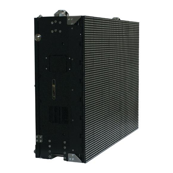
OLite control box mounted inside the OLite rental frame. The control box has a MDR input and a MDR output port to connect the OLite rental tile with the neighboring tiles in the display. Image 4-1 OLite 510 rental tile (R9010330) OLite 510 rental frame. OLite control box. -
Page 16: Olite Module
Receiver for side locking mechanism. G Rugged handle for operating top-bottom locking mechanism. Removable mounting plate for OLite control box. Grid to snap in the OLite 510 modules. Small handle for operating side locking mechanism. 4.2 OLite module Introduction OLite module The front of an OLite module consists of a matrix of full color SMD LED’s enclosed with a shader and sheltered in an IP65 housing. - Page 17 4. Components of an OLite rental tile Image 4-3 OLite 510 module (R9853020). Parts location of an OLite module Image 4-4 OLite 510 module (R9853020). Shader. Full color LED. Module positioning pin. External fan cover. Snap-in latch. Hole for thread rolling screw M3.
-
Page 18: Olite Control Box
The power supply requires an input voltage between 200 and 240 volt AC. The distribution interface has 6 output ports to connect a string of OLite modules with using an OLite cable string. The re-sync unit contains the standard Barco LED-wall outdoor connector ports to link the data and power from tile to tile. - Page 19 Power cables used between OLite control boxes To meet the demands of each OLite application Barco offers several lengths of power cables to link power from control box to control box. Note that the power output port of the last OLite control box in the power chain has to be sealed with a dummy power plug.
- Page 20 Data cables used between OLite control boxes To meet the demands of each OLite application Barco offers several lengths of data cables to link data from control box to control box. Note that the data output port of the last OLite control box in the data chain has to be sealed with a dummy data plug.
- Page 21 4. Components of an OLite rental tile Dummy plug for unused power/data output ports Image 4-18 Dummy plug (Z3499467) for unused output ports of the OLite control box. R5976832 OLITE RENTAL DISPLAY 15/12/2004...
- Page 22 4. Components of an OLite rental tile R5976832 OLITE RENTAL DISPLAY 15/12/2004...
-
Page 23: Olite Rental Peripherals And Accessories
5. OLite rental peripherals and accessories 5. OLITE RENTAL PERIPHERALS AND ACCESSORIES 5.1 OLite rental flight case Introduction of the OLite rental flight case The OLite rental flight case holds up to 4 tiles and is specially designed to enable fast build up directly from flight case to display. The tiles inside the flight case are separated with a removable partition plate. -
Page 24: Olite Rental Base Stand Setup Accessories
5. OLite rental peripherals and accessories Parts location of the OLite rental flight case Image 5-3 Flight case cover. Cover locking handle. Cover positioning strip. Removable partition plate. Cover locking receiver. Forklift slot. G Stacking dish. Carrying handle. Tile positioning cone. 5.2 OLite rental base stand setup accessories Base stand setup accessories To setup an OLite rental display in a base stand configuration additional mounting accessories are required as there are the foot... -
Page 25: Olite Rental Truss Setup Accessories
Truss setup accessories OLite truss beams are required to set up an OLite rental display in a hanging configuration. Barco offers two sizes of OLite truss beams, namely the “OLite single truss beam” and the “OLite dual truss beam”. The single truss beam covers a width of one OLite tile and the dual truss beam covers two tiles. -
Page 26: Power Boxes
The control software is designed as a graphic user interface (GUI) and can be used to control and configure the digitizer as well as the Barco LED wall via a PC (e.g. XLite Toolset). Refer to the manual of the control software for more information about the control software. -
Page 27: Set Up Process Of An Olite Rental Display
6. Set up process of an OLite rental display 6. SET UP PROCESS OF AN OLITE RENTAL DISPLAY About this chapter This chapter describes roughly the installation process of the OLite rental display for a base stand (floor mount) or truss (hanging) configuration. - Page 28 6. Set up process of an OLite rental display 6. Data cabling of the OLite rental display. See chapter "Data cabling of an OLite rental display", page 45. 7. Installation of the control software for the OLite rental display. See installation procedure described in the manual of the control software.
-
Page 29: Basic Set Up Procedures
7. Basic set up procedures 7. BASIC SET UP PROCEDURES About this chapter This chapter contains all installation procedures necessary to set up an OLite rental display. These procedures describe, with de- tailed step by step actions and illustrations, how to install an OLite rental display in a floor mount or hanging configuration. Some of the procedures are redundant either for a floor mount or a hanging configuration. -
Page 30: Place Olite Rental Tiles Into The Flight Case
7. Basic set up procedures Image 7-2 Unlock outer tile in flight case and lift the tile up. Tip: You can use a hoisting crane to lift up the OLite rental tile. First attach an OLite truss beam upon the OLite rental tile and then lift up the truss beam. -
Page 31: Install The Olite Rental Feet
7. Basic set up procedures Image 7-4 Secure the OLite rental tile with the flight case trolley. 5. Place a partition plate at the front and at the back of the secured OLite rental tile. This is necessary to protect the OLite rental tile while placing other tiles on the flight case trolley. -
Page 32: Install An Adjustable Foot
7. Basic set up procedures Image 7-6 Install rental foot. Foot beam. Foot beam slot. Rental foot rail. Rental foot 3. Slide the rental foot with attached rails into the slots of the foot beams. Ensure the front side of the foot will be at the same side as the LED’s. -
Page 33: Attach An Olite Truss Beam Upon An Olite Rental Tile
7. Basic set up procedures Image 7-8 Attachment with cross beam. Height adjustment. 3. Attach the adjustable foot to the cross beam using an Allen key of 4 mm. 4. Slide an adjustable foot into the other end of the cross beam. 5. -
Page 34: Attach An Olite Rental Tile Upon An Olite Rental Foot
7. Basic set up procedures Image 7-10 Place the handles of the truss bean in the locked position. 7.6 Attach an OLite rental tile upon an OLite rental foot How to attach an OLite rental tile upon an OLite rental foot ? 1. -
Page 35: Attach Olite Rental Tiles On Top Of Each Other
7. Basic set up procedures 7.7 Attach OLite rental tiles on top of each other How to attach OLite rental tiles on top of each other ? 1. Ensure that both locking mechanisms at the bottom of the OLite rental tile are unlocked. So, handles in vertical position and pulled out. -
Page 36: Install An Olite Stacker System
7. Basic set up procedures Image 7-15 Turn the small handle clockwise as far as possible. 2. Bring the two OLite tiles together and close the adjoining side latch hook by turning the small handle as for a possible counter- clockwise. - Page 37 7. Basic set up procedures Image 7-17 Install stacker foot. Stacker foot. Stacker foot rail. M12 bolt. 3. Move the stacker foot forwards against the OLite rental foot and secure the eight bolts tightly. 4. Place the stacker bridge into position and secure the bridge with a lock key and two spring cotters. Note: The small handle to operate the side locking mechanism has to stand in vertical position, otherwise the handle gets in the way to install the stacker bridge.
-
Page 38: Secure A Hanging Olite Rental Display
7. Basic set up procedures Image 7-19 Install stacker profile. 6. Secure the stacker profile with the foot and the bridge using two lock keys and four spring cotters. ARNING Ensure that each lock key is secured with two spring cotters. 7.10 Secure a hanging OLite rental display Necessary parts Safety steel cables or chains. -
Page 39: Build Up A Floor Mounted Olite Rental Display
7. Basic set up procedures >45° Image 7-20 Secure a hanging OLite rental display. Hoist steal cable or steel chain. Hoist eye bolt. Safety steal cable or safety steel chain. Safety eye bolt. 7.11 Build up a floor mounted OLite rental display Floor mounted OLite display A floor mounted OLite rental display is built upon OLite rental feet. - Page 40 7. Basic set up procedures How to build up a floor mounted OLite rental display ? 1. Ensure you understand and follow all the safety guidelines, safety instructions and warnings mentioned in the chapter "Safety", page 3 of this manual. 2.
- Page 41 7. Basic set up procedures Image 7-26 Install stacker system. 5. Install the next two rows of OLite rental tiles. Ensure each tile is attached and locked correctly. Image 7-27 Install the next two rows. 6. Install an OLite stacker upon the previous installed stacker. Note: Only the vertical stacker profile and the stacker bridge have to be installed now.
-
Page 42: Build Up A Hanging Olite Rental Display With Truss Beams
7. Basic set up procedures 7.12 Build up a hanging OLite rental display with truss beams Hanging OLite rental display A hanging OLite rental display is built up row by row. Each row is built by placing the OLite rental flight cases next to each other and fastening the OLite tiles side by side. - Page 43 7. Basic set up procedures Image 7-32 Unlock the tiles from the flight case. Image 7-31 Install truss beams upon the outer row of tiles. 6. Lift up the complete OLite row out of the flight cases. Image 7-33 Lift up the complete OLite row out of the flight cases. 7.
- Page 44 7. Basic set up procedures Image 7-35 Lift up row one and two. 10.Repeat from step 7 until the complete OLite display is constructed. Image 7-37 Place the next row of tiles underneath the suspended rows. Image 7-36 Rotated the flight cases and construct a new row of tiles. R5976832 OLITE RENTAL DISPLAY 15/12/2004...
- Page 45 7. Basic set up procedures Image 7-39 Place the next row of tiles underneath the suspended rows. Image 7-38 Attach and lift up the next row of tiles. Image 7-40 Attach and lift up the next row of tiles. ARNING The maximum height of a hanging OLite rental display is 15 tiles high.
- Page 46 7. Basic set up procedures R5976832 OLITE RENTAL DISPLAY 15/12/2004...
-
Page 47: Cabling Of An Olite Rental Display
Power boxes Barco provides several types of power boxes. Depending on the size of the OLite rental display you can choose to use the mono phase power box or the custom made power box or the rental power box. The type of power box, does not influence the power cabling of the OLite rental display. - Page 48 8. Cabling of an OLite rental display ARNING To protect against risk of fire by overloading of power cables, the amount of OLite tiles per power source cable is limited. Never connect more than 2 OLite tiles with a power source cable. Necessary parts •...
-
Page 49: Data Cabling Of An Olite Rental Display
When using a fiberlink system the fiberlink data connection is inserted between the digitizer and the first OLite tile. The fiberlink receiver is also equipped with Barco’s outdoor connector sockets. When using a Ambient Environment Controller (AEC) the data connection of the AEC is inserted between two OLite tiles. -
Page 50: Module Interconnection Of An Olite 510 Rental Frame
The OLite 510 rental frame contains eight columns of eight OLite 510 modules. These columns are grouped per two and ordered from right to left, seen from the rear of the tile. A cable string is used to connect all 16 OLite 510 modules of one group with the OLite control box, see illustration below. - Page 51 8. Cabling of an OLite rental display Image 8-5 Insert the plug into the socket and turn the locking cap as far as possible. Warning: Ensure that the locking cap of each plug is turned clockwise as far as possible until you feel a “click”. 4.
- Page 52 8. Cabling of an OLite rental display R5976832 OLITE RENTAL DISPLAY 15/12/2004...
-
Page 53: Maintenance
9. Maintenance 9. MAINTENANCE 9.1 Cleaning OLite tiles Why cleaning OLite tiles ? Due to outdoor use the OLite tiles are exposed to all kinds of weather conditions. Sand, dust, smog and other dirt adhere on the OLite tiles and because of that the performance of the OLite tiles is reduced. That’s why cleaning the OLite tiles is recommended at regular intervals. - Page 54 9. Maintenance R5976832 OLITE RENTAL DISPLAY 15/12/2004...
-
Page 55: Servicing
Inspect the complete LED-wall for security, wear, deformation, corrosion, and any other circumstances that may affect the load handling capability of the part. • Do not modify and/or replicate any component. Barco uses specific materials and manufacturing processes in order to achieve part strength. No other parts than Barco parts are allowed. •... -
Page 56: Replace The Olite Control Box
10. Servicing Image 10-1 Location of status LED’s on the OLite module. Red colored status LED. G Green colored status LED. Diagnostic Red LED Green LED Diagnostic Action OLite module has no power Check connections with cable string. Flashing Software of the OLite module is Replace OLite module. -
Page 57: Replace An Olite Module Without Replacement Tool
10. Servicing Image 10-3 Remove the control box. 6. Place a new OLite control box with mounting plate in the same position as the previous removed control box. 7. Secure the control box with mounting plate by sliding the mounting plate to the left as far as possible. Warning: Ensure the mounting plate is locked. - Page 58 10. Servicing Image 10-5 Release the OLite module from the grid. 4. Guide your hand with the OLite module further through the grid opening and rotate the module. Image 10-6 Pull back the OLite module through the grid. 5. Hand over the released OLite module in front of the tile. Note: It’s possible to pull back the OLite module through the grid opening if required..
-
Page 59: A. Dimensions
A. Dimensions A. DIMENSIONS A.1 Dimensions of an OLite rental tile Dimensions OLite frame 896 mm 246 mm 294 mm Image A-1 Dimensions OLite frame with modules 896 mm 262,42 mm 310,42 mm Image A-2 R5976832 OLITE RENTAL DISPLAY 15/12/2004... -
Page 60: A.2 Dimensions Of An Olite Module
A. Dimensions A.2 Dimensions of an OLite module Dimensions 16,42 111,6 52,5 Image A-3 Dimensions given in millimeters. A.3 Dimensions of an OLite control box Dimensions 296,5 132,6 Image A-4 Dimensions given in millimeters. R5976832 OLITE RENTAL DISPLAY 15/12/2004... -
Page 61: A.4 Dimensions Of An Olite Flight Case
A. Dimensions A.4 Dimensions of an OLite flight case Dimensions 1384 mm 960 mm 1440 mm 880 mm Image A-5 A.5 Dimensions of an OLite truss beam Dimensions single truss beam Image A-6 Dimensions given in millimeters. R5976832 OLITE RENTAL DISPLAY 15/12/2004... -
Page 62: A.6 Dimensions Of An Olite Foot
A. Dimensions Dimensions dual truss beam 1787 Image A-7 Dimensions given in millimeters. A.6 Dimensions of an OLite foot Dimensions Image A-8 Dimensions given in millimeters. R5976832 OLITE RENTAL DISPLAY 15/12/2004... -
Page 63: A.7 Dimensions Of An Olite Stacker System
A. Dimensions A.7 Dimensions of an OLite stacker system Dimensions stacker foot 690 mm 119,15 mm Image A-9 Dimensions stacker profile 1394 mm 200 mm Image A-10 Dimensions stacker bridge 602 mm 117,6 mm Image A-11 R5976832 OLITE RENTAL DISPLAY 15/12/2004... - Page 64 A. Dimensions R5976832 OLITE RENTAL DISPLAY 15/12/2004...
-
Page 65: B. Specifications
B. Specifications B. SPECIFICATIONS B.1 Specifications of the OLite 510 rental tile Specifications Lifetime 50.000 h (full white - half brightness) Pixel pitch 10 mm Brightness 6000 NIT Calibrated Brightness 5000 NIT (calibrated at 6500K) LED configuration 3-in-1 SMD Pixel density 9.354/m²... -
Page 66: B.2 Ballast Values For An Base Stand Olite Display
All calculations are based upon a wind load of 0,8 kN/m² (±129 km/h) which comply with the TUV regulations. For more information consult the “Ballast calculator” tool, available on Barco’s web site. The ballast values are given per OLite rental foot mounted upon two foot beams. Ballast must be placed upon the last 30 cm of the foot beams. -
Page 67: B.3 Ground Pressure Of A Base Stand Olite Display
All calculations are based upon a wind load of 0,8 kN/m² (±129 km/h) which comply with the TUV regulations. For more information consult the “Ballast calculator” tool, available on Barco’s web site. The ballast values are given per OLite rental foot mounted upon two foot beams. Ballast must be placed upon the last 30 cm of the foot beams. - Page 68 B. Specifications Ground pressure of an OLite display installed in the middle of the foot beams Single OLite rental foot 1,2 meter foot beams 2,4 meter foot beams 4 meter foot beams Height kg/cm² N/mm² kg/cm² N/mm² kg/cm² N/mm² Tiles 0,01923 0,00189 0,00561...
-
Page 69: C. Order Info
C. Order info C. ORDER INFO C.1 Spare part order info Order info: Order info Description R9010330 Complete OLite 510 rental tile (controller and modules included) R9853010 OLite 510 rental frame (empty) R9853020 OLite 510 module R98530205 OLite 510 module (5 pieces) - Page 70 C. Order info R5976832 OLITE RENTAL DISPLAY 15/12/2004...
-
Page 71: Index
Floor mount Hanging Set up process Software System requirements Important warnings 4–5 Spare parts Flight case Specifications Install 27–28, 32 OLite 510 Adjustable foot OLite feet OLite stacker Installation Requirements Truss 21, 23 Introduction Accessories R5976832 OLITE RENTAL DISPLAY 15/12/2004...
Need help?
Do you have a question about the OLite 510 and is the answer not in the manual?
Questions and answers