
Related Manuals for Parker Zander K-MT 1/D3


Summary of Contents for Parker Zander K-MT 1/D3
- Page 1 Adsorption dryer K-MT 1-4/D3 ( Generation - 3) Operating manual Revisione 0 —2018 /EN Cod: 398H272183...
-
Page 3: Table Of Contents
EN | User Manual Index Machine passport General information Manufacturer’s details ......................4 Details on the dryer ........................4 About these operating instructions ................... 5 For your own safety General safety notes ......................... 6 Intended use of the dryer ......................7 Signs and hazard areas on the dryer .................. - Page 4 EN | User Manual Annex with technical documentation Technical data ......................... 47 Replacement and wear part list ....................48 Logic control diagram ......................49 Flow diagram .......................... 51 Dimensional drawing ......................52 K-MT 1-4/D3...
-
Page 5: Machine Passport
EN | User Manual Machine passport Machine passport It is the responsibility of the owner, ◊ to enter for the fi rst time any appliance data not stated above, ◊ to keep these appliance data up to date. The above-stated appliance data provide for a clear identifi cation of the dryer and its compo- nents, and signifi cantly facilitate any service measures. -
Page 6: General Information
EN | User Manual General information General information Manufacturer’s details Name and address Parker Hannifi n Manufacturing S.r.l. Sede Legale: Via Privata Archimede, 1- 2009 Corsico (MI) Italy Sede Operativa: Gas Separation and Filtration Division EMEA - Strada Zona Industriale, 4 35020 S.Angelo di Piove (PD) Italy tel +39 049 971 2111- fax +39 049 9701911 Web-site: www. -
Page 7: About These Operating Instructions
EN | User Manual General information About these operating instructions These operating instructions contain basic information on the safe use of the dryer. Characters and symbols used Work steps that you have to carry out in the sequence stated are marked by black tri- angles. -
Page 8: For Your Own Safety
EN | User Manual For your own safety For your own safety The dryer has been built in accordance with the state of the art and the recognized technical safety regulations. Nevertheless, there is a risk of personal injury and damage to property when the dryer is used, if ◊... -
Page 9: Intended Use Of The Dryer
EN | User Manual For your own safety Disassembly and disposal ◊ Dispose all parts of the dryer, the drying agent, and all other operating materials in an envi- ronmentally safe way and in accordance with all current statutory regulations. Intended use of the dryer The dryer is exclusively intended for drying compressed air. -
Page 10: Signs And Hazard Areas On The Dryer
EN | User Manual For your own safety Signs and hazard areas on the dryer Signs and labels Operating data plate Type plate of dryer Type plate of downstream fi lter Type plate of upstream fi lter Front view Please note the above plates and instructions attached to the dryer. Ensure that they are not removed and are always readable. - Page 11 EN | User Manual For your own safety Hazard caused by overpressure Hazard caused by electrical voltage Hazard caused by sudden air ejection during expansion Risk of damage to eyes Symbol Hazard area Warning against hazardous electrical voltage Different parts of the dryer carry electrical current. These parts may be connected, opened, and maintained by authorized specialist personnel only.
-
Page 12: Transportation, Installation And Storage
EN | User Manual Transportation, installation and storage Transportation, installation and storage Danger due to incorrect transportation! The dryer must be transported by authorized and qualifi ed specialist personnel only. During transportation all applicable national regulations for accident pre- vention must be complied with. Otherwise there is a risk of personal injury. Always adhere to the stickers and notes on the packaging of the dryer! ◊... -
Page 13: Transporting And Installing The Dryer
EN | User Manual Transportation, installation and storage Transporting and installing the dryer Requirements for the installation site The conditions at the installation site have a large infl uence on the functional capability of the dryer and the service life of the drying agent. In order to ensure a mode of operation, which is as continuous as possible, and low maintenance, the installation site must meet the following requirements: ◊... - Page 14 EN | User Manual Transportation, installation and storage Secure the cardboard box or pallet on the lifting or forklift truck against sliding move- ments. Transport the dryer to its installation site. Remove the packaging of the dryer Carefully place the dryer in an upright position. Place the dryer at its installation site.
-
Page 15: Storing The Dryer
EN | User Manual Transportation, installation and storage Storing the dryer If the dryer is to be stored for an extended period of time, the storage location must meet the following conditions: ◊ The dryer must not be stored in the open air. ◊... -
Page 16: Technical Product Description
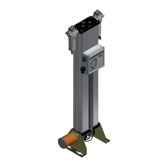
EN | User Manual Technical product description Technical product description Summary drawing Front view Regeneration gas return Dewpoint sensor (optional) RV3–RV4 (Option) Check valve plate (RV1–RV2) Compressed air outlet Compressed air inlet Upstream fi lter Downstream fi lter Condensate trap Manual drain valve ON/OFF switch Control box with Multitronic... - Page 17 EN | User Manual Technical product description Adsorption Via a compressor, humid compressed air is supplied to the upstream fi lter. From here, the compressed air fl ows upwards through the absorption chamber, which is pressurised. In so doing, the drying agent dehumidifi es the air. The dry compressed air is supplied to the pipe network via the downstream fi lter.
- Page 18 EN | User Manual Technical product description Pressure build-up phase After dehumidifi cation the pressure in the regenerated hollow section vessel is built up to operating pressure, so that the switchover from regeneration to adsorption can take place at operating pressure level. Pressure build-up Standby phase (only with the dewpoint-sensing control option) When in standby phase, the fully regenerated vessel is ready for absorption operation.
-
Page 19: Available Options
EN | User Manual Technical product description Available options The following options are available for the dryer: ◊ Start-up device ◊ Signalling contacts of the control system & compressor synchronisation ◊ Regeneration gas return ◊ Dewpoint-sensing control ◊ Fine fi lter muffl er ◊... - Page 20 EN | User Manual Technical product description Nozzle kit In the case that the operating pressure deviates from the standard design pressure (7bare) it is possible that the amount of necessary regeneration air changes. This effect may have a negative impact on the cost-effectiveness of the dryer. To prevent this, it is possible to replace the built in regeneration air nozzle by a nozzle with a modifi ed bore.
-
Page 21: Installation
EN | User Manual Installation Installation Warning against hazardous electrical voltage Different parts of the dryer carry electrical current. These parts may be connected, opened, and maintained by authorized specialist personnel only. As soon as the dryer has been set up at its installation location, you can install the com- pressed air infeed and outlet lines make the electrical connections. -
Page 22: Connect Piping
EN | User Manual Installation Connect piping In order to ensure that the dryer operates optimally, the dryer must be assembled into the compressed air system free of all stresses. Ensure before connection that all infeed and outfeed compressed air lines and valves are clean and undamaged. -
Page 23: Installing The Electrical Connection
EN | User Manual Installation Installing the electrical connection Warning against electrical voltage Only qualifi ed specialist personnel may carry out work on the electrical system! Installing the supply cable The components of the dryer have been connected to the control cabinet at the factory. You only need to connect the control cabinet to the electrical supply cable. - Page 24 EN | User Manual Installation Connecting the external signalling lines For compressor synchronisation The controller is fi tted as standard with a digital input which makes the dryer regeneration dependent on operation of the compressor (switch S1 on the controller’s circuit board, see also fi gure below).
-
Page 25: Start-Up
EN | User Manual Start-up Start-up ◊ Carry out all prescribed tests and checks. ◊ Before start-up, ensure that no tools or other foreign parts have been left lying in a part of the dryer where they might pose a hazard to the dryer being started up. Requirements for initial start-up For the fi rst start-up the following preconditions must have been met: ◊... -
Page 26: Overview Of Operating And Control Elements
EN | User Manual Start-up Overview of operating and control elements ON/OFF switch The ON/OFF switch (2) is located to the side of the switchbox and above the mains plug (1, see fi gure): ◊ If it is set to 0, the power supply is disconnected and the dryer is switched off. The main valves are (V1, V2) are open, while the expansion valves (V3, V4) are closed. - Page 27 EN | User Manual Start-up LED Power (1) LED is on when dryer is switched on. Flow diagram (2) The current operating phases of the dryer are indicated by means of 4 LEDs: Vessel B2 Vessel B1 Regeneration 2 Regeneration 1 Adsorption 2 Adsorption 1 Depending on the operating phase, the following LEDs might be on simultaneously:...
- Page 28 EN | User Manual Start-up This LED is only relevant in units that are equipped with the optional dewpoint-sensing control. The diode lights up when the dryer is switched on and in the standby phase and no regeneration air is required. K-MT 1-4/D3...
-
Page 29: Start Up Dryer
EN | User Manual Start-up Start up dryer Warning against sudden air ejection! During expansion the pressure is released suddenly through the muffl er: ◊ A loud cracking noise occurs which can injure your hearing. ◊ Particles carried in the air fl ow act like bullets and can injure your eyes or skin. - Page 30 EN | User Manual Start-up Ensure that the compressed air outlet valve installed by the owner is closed. Keep the compressed air outlet valve closed for the time period recommended above. Then the dryer can be taken into service in the compressed air system as described in the following section: Operate dryer immediately in the compressed air system Ensure that the compressed air system downstream of the dryer is pressurised or that a...
-
Page 31: Changing Cycle Mode (Optional)
EN | User Manual Start-up Changing cycle mode (optional) When can I change cycle mode? If the dryer has been successfully commissioned and is equipped with one of the following options: ◊ compressor synchronisation or ◊ dewpoint-sensing control it can be set to economy cycle mode. When should I change cycle mode? Cycle changes should be made during the pressure build-up phase and prior to switchover;... -
Page 32: Monitoring Dryer Operation
EN | User Manual Monitoring dryer operation Monitoring dryer operation The dryer operates fully automatically. However, you should carry out the regular checks described in the Chapter Maintenance and repair of the dryer. Warning against sudden air ejection! During expansion the pressure is released suddenly through the muffl er: ◊... -
Page 33: Shutdown And Restart Dryer
EN | User Manual Shutdown and restart dryer Shutdown and restart dryer In the following cases, the dryer must be fully shut down and depressurised: ◊ In the event of an emergency or malfunction ◊ For maintenance work ◊ For dismantling Caution! Risk of damage to the dryer, if it is switched off during the expansion or drying phase. -
Page 34: If Work Is To Be Carried Out On The Electrical System
EN | User Manual Shutdown and restart dryer If work is to be carried out on the electrical system Depressurise and shut down the dryer, following the instructions in the above chapter. Risk of injury due to voltage-carrying parts! The electrical supply cable and external power lines are live even after the dryer is switched off and, in the event of body contact, may cause serious injury! Before carrying out any work on the electrical system, the electrical supply cable and all external power lines must be made voltage-free! -
Page 35: Maintenance And Repair Of The Dryer
EN | User Manual Maintenance and repair of the dryer Maintenance and repair of the dryer In order to allow maintenance work on the dryer to be carried out effi ciently and without dan- ger for maintenance personnel, you should comply with the following instructions. Notes on maintenance Danger! There is a very considerable risk of personal injury, when carrying out work on... -
Page 36: Regular Maintenance Intervals
EN | User Manual Maintenance and repair of the dryer Regular maintenance intervals Note: If a chamber has been depressurised, e.g. after completion of the ex-pansion phase, and the pressure remains above 0 bar, the chamber is pressurised by what is known as ram pressure. This might be due to ◊... -
Page 37: Instructions For Use Of The Dongle
EN | User Manual Maintenance and repair of the dryer Instructions for use of the dongle If the message SEr, is displayed on the display of the Multitronic controller, the dryer is due for servicing. The message appears, fl ashing every 60 seconds, once the preset number of operating hours (e. -
Page 38: Maintenance Work To Be Completed Every 12 Months
EN | User Manual Maintenance and repair of the dryer Maintenance work to be completed every 12 months Check muffl ers The dryer is either equipped with a standard muffl er or a fi ne fi lter muffl er. If the respective muffl er becomes blocked, a dam pressure is generated which in extreme cases may cause the muffl er to burst. - Page 39 EN | User Manual Maintenance and repair of the dryer Replace the element in the fi ne fi lter muffl er Depressurise the dryer and shut it down (see page 31 ). Undo knurled screw on the lid cap and remove cap.
-
Page 40: Maintenance Work To Be Completed Every 24 Months
EN | User Manual Maintenance and repair of the dryer seal. Remove dewpoint sensor from the sensor cell (3) by turning the nut (2). Take the new dewpoint sensor (2) from the box, remove the protective caps (4, 5) and screw it into the sensor chamber (3). - Page 41 EN | User Manual Maintenance and repair of the dryer Replace solenoid valves Solenoid valves are wear parts and must thus be replaced every 48 months, even if no dam- age is visible. Release pressure from dryer and shut down the unit (see page 31 ).
- Page 42 EN | User Manual Maintenance and repair of the dryer Depressurise the dryer and shut it down (see page 31 ). Loosen the screws at the check valve plate and lift off the plate. Removing and replacing, perforated plate and pressure springs. Before reassembling the check valve plate, you should replace the drying agent.
- Page 43 EN | User Manual Maintenance and repair of the dryer Replacing the lower perforated plate Loosen the screws on the solenoid valve plate. Remove and replace perforated plate and demisters. Loosen the solenoid valve plate Reaffi x the solenoid valve plate: Use a dyamometric key to tighten the screws, and take care to observe the following torques:...
- Page 44 EN | User Manual Maintenance and repair of the dryer Subsequently, position the perforated plate onto the check valve plate, align them proper- ly and secure them. Reaffi x the check valve plate: Use a dyamometric key to tighten the screws, and take care to observe the following torques: —...
-
Page 45: Identify And Eliminate Faults
EN | User Manual Identify and eliminate faults Identify and eliminate faults The following table provides information on what designatory abbreviations are to be used for the various components. These designations are also found in the technical documentation. Used abbreviation Component Differential pressure gauge V1–V2 (Y2–Y1) - Page 46 EN | User Manual Identify and eliminate faults Fault Possible cause Remedy Dryer cannot be Solenoid valve Y1/Y2 can- Check supply voltage, ca- • • switched over not be opened. ble, contacts and solenoid; replace, if necessary. Solenoid valve Y1/Y2 can- Check supply voltage.
- Page 47 EN | User Manual Identify and eliminate faults With dewpoint-sensing control (optional) Fault code Description of Possible cause Remedy fault Upper measuring Drying capacity See instructions for range limit exceeded exceeded. commissioning. If the drying agent is wet, • replace it. Error in programme.
-
Page 48: Annex With Technical Documentation
EN | User Manual Annex with technical documentation Annex with technical documentation This annex comprises the following information and technical documentation: ◊ Technical data ◊ Replacement and wear parts list ◊ Logic control diagram ◊ Flow diagram ◊ Dimensional drawing K-MT 1-4/D3... -
Page 49: Technical Data
EN | User Manual Annex with technical documentation Technical data Operating Range Site Selection frost-free indoor installation in a non-hazardous environment Ambient temperature 1,5 to 50 °C (24,7 to 122 °F) Compressed air inlet temperature 25 to 50 °C (68 to 122 °F) Max. -
Page 50: Replacement And Wear Part List
EN | User Manual Annex with technical documentation Replacement and wear part list Note: When exchange or replacement parts are ordered, always state the dryer type and the build no. of the dryer. These data are found on the type plate. Service-kits For model Maintenance-... -
Page 51: Logic Control Diagram
EN | User Manual Annex with technical documentation Logic control diagram Adsorption in B1 and regeneration in B2 K-MT 1-4/D3... - Page 52 EN | User Manual Annex with technical documentation Regeneration in B1 and adsorption in B2 K-MT 1-4/D3...
-
Page 53: Flow Diagram
EN | User Manual Annex with technical documentation Flow diagram Item Designation Item Designation Check valve plate Control unit 10.101 Seal Control system 10.102 Perforated plate Upstream fi lter 10.107 Demister, left Downstream fi lter 10.108 Demister, right Muffl er 10.109 Left perforated plate Optional devices:... -
Page 54: Dimensional Drawing
EN | User Manual Annex with technical documentation Dimensional drawing Installation on fl oor BSP-P/ Dimensions [mm] Weight [kg] Type K-MT 1 1/4" 11,5 K-MT 2 1/4" 15,5 K-MT 3 1/4" 20,0 K-MT 4 1/4" 1075 1051 25,0 K-MT 1-4/D3... - Page 56 A division of Parker Hannifin Corporation Parker Hannifin Manufacturing S.r.l. Sede Legale: Via Privata Archimede, 1- 2009 Corsico (MI) Italy Sede Operativa: Gas Separation and Filtration Division EMEA - Strada Zona Industriale, 4 35020 S.Angelo di Piove (PD) Italy tel +39 049 971 2111- fax +39 049 9701911 Web-site: www.
Need help?
Do you have a question about the K-MT 1/D3 and is the answer not in the manual?
Questions and answers