
Related Manuals for Parker Zander HDK-MT 15/100


Summary of Contents for Parker Zander HDK-MT 15/100
- Page 1 High Pressure Dryer HDK-MT 15/100—70/100 15/350—70/350 Operating Instructions Revision 06—07-2016 /EN...
- Page 2 D – 45219 Essen Kettwig hereby declares with sole responsibility, that the products High-pressure Dryer Series HDK-MT 15/100 to 70/350 Assembly type: assembly acc. to Art. 4 No. 2b, which this declaration refers to, conform to Directive 2014/68/EU and were subjected to a conformity assessment according to Annex III Modules B + D (for assembly assessment).
- Page 3 Piping (100 / 350 bar) Dryer Allowable Dimensions Category Module pressure (PS) (DN) (PED) HDK-MT 15 / … DN15 Art.4.3 Art.4.3 HDK-MT 20 / … DN15 Art.4.3 Art.4.3 HDK-MT 25 / … DN15 Art.4.3 Art.4.3 HDK-MT 30 / … DN15 Art.4.3 Art.4.3 HDK-MT 40 / …...
- Page 4 Machine passport It is the responsibility of the owner, to enter for the first time any appliance data not stated above, to keep these appliance data up to date. Type designation HDK-MT__ Order no. Project no. Build no. Vessel no.
-
Page 5: Table Of Contents
Table of contents General Information..................... 7 Manufacturer's details ......................7 Details on the dryer ........................ 7 About these operating instructions ..................8 Intended use of the dryer ....................... 9 For your own safety..................... 9 General safety notes ......................10 Signs and hazard areas on the dryer ................... 12 Technical Description .................. - Page 6 Maintenance and repair of the dryer ..............37 Notes on maintenance ......................37 Regular maintenance intervals ..................... 38 Instructions for use of the dongle ..................39 HDK-MT special tool kit ......................40 Perform a weekly visual inspection ..................41 Maintenance work to be completed every 12 months ............42 Maintenance work to be completed every 24 months ............
-
Page 7: General Information
General Information Manufacturer's details Name and address Details on the dryer Standard scope of delivery Dryer, comprising 2 towers with a top and bottom valve block. filled with desiccant 1 prefilter 1 after-filter 1 muffler 1 dewpoint sensor ... -
Page 8: About These Operating Instructions
About these operating instructions These operating instructions contain basic information on the safe use of the dryer. Characters and symbols used ► Work steps that you have to carry out in the sequence stated are marked by black triangles. Lists are marked by a small box. -
Page 9: Intended Use Of The Dryer
For your own safety The dryer has been built in accordance with the state of the art and the recognized technical safety regulations. Nevertheless, there is a risk of personal injury and damage to property when the dryer is used, if ... -
Page 10: General Safety Notes
General safety notes For your own safety, when carrying out any work on the dryer comply with all applicable national safety regulations! Risk of injury from escaping compressed air! Never remove any parts of the dryer, or manipulate the same in any way, for as long as the plant is still pressurised! Suddenly escaping compressed air might cause serious injuries. - Page 11 Personnel qualification Only authorized and qualified specialist personnel may be tasked with the work on the dryer described in these operating instructions. The operating personnel must have been trained by the manufacturer or a distributor. Conversions and modifications Without prior approval by the manufacturer, no conversions and modifications must be made to the dryer! Any non-approved modifications may restrict the operational safety of the dryer and cause damage to property or personal injury.
-
Page 12: Signs And Hazard Areas On The Dryer
Signs and hazard areas on the dryer Signs and labels Label with setting pressure of start-up device (option) Label with setting value for regeneration gas Filter ratings plates Type plate of the dryer Front view Please note these signs on the dryer. Keep them complete and always legible.Keep them complete and always legible. - Page 13 Hazard areas on the dryer Symbol in operating Hazard area instructions Warning against hazardous electrical voltage Different parts of the dryer carry electrical current. These parts may be connected, opened, and maintained by authorized specialist personnel only. Warning against overpressure The entire dryer is under pressure.
-
Page 14: Technical Description
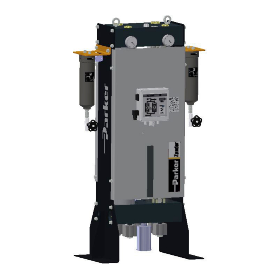
Technical Description Layout Front view Check valve block Vessel pressure gauge Regeneration gas return connection (option) Compressed air inlet Start-up device (option) Prefilter Compressed air outlet Control system ON/OFF switch Power connector Muffler Solenoid valve block Differential pressure gauge Transport lugs (option) Vessel Dewpoint sensor... -
Page 15: Function
Function The dryer dries the compressed air supplied by the compressor and makes it available for industrial use. The installed prefilter and after-filter clean the compressed air supplied to the dryer and the compressed air from the dryer to the consumers. The two vessels contain extremely porous desiccants by means of which humidity is removed from the compressed air and stored just as in a sponge. -
Page 16: Standard Equipment
Pressure build-up phase After dehumidification the pressure in the regenerated hollow section vessel is built up to operating pressure, so that the switchover from regeneration to adsorption can take place at operating pressure level. Switchover When the desiccant in the adsorbing vessel has taken up a sufficient level of humidity, then the switchover between the vessels will be effected between the vessels. - Page 17 A start-up device protects the dryer from excessively high flow rates as it only opens after reaching a preset minimum pressure of approx. 80%, thus maintaining adequate operating pressure in the dryer. A T-piece is supplied with the start-up device, to which the regeneration gas return can be connected.
-
Page 18: Transportation, Installation And Storage
Transportation, installation and storage Danger due to incorrect transportation! The dryer must be transported by authorized and qualified specialist personnel only. During transportation all applicable national regulations for accident prevention must be complied with. Otherwise there is a risk of personal injury. Danger of toppling over! The dryer has a very high centre of gravity. -
Page 19: Transporting The Dryer To Its Installation Site
Transporting the dryer to its installation site Warning - lifting dryer contrary to instructions! Lifting the dryer contrary to instructions can cause damage. Lift the dryer only with the supplied lifting eyebolts! Transport lugs Transportation using lifting or forklift truck Warning against damage to property! The dryer is supplied upright on a pallet. - Page 20 The installation area must be level, firm and vibration-proof. It must have the necessary carrying capacity for the weight of the dryer. The weight of the dryer is specified in the technical data section of the annex. The dryer should be installed with sufficient spacing at the top, sides, and rear, in order to be able to carry out maintenance work and change the desiccant without any hindrances.
-
Page 21: Storing The Dryer
Storing the dryer If the dryer is to be stored for an extended period of time, the storage location must meet the following conditions: The dryer must not be stored in the open air. The storage room must be dry. ... -
Page 22: Installation
Installation Only authorized and qualified specialist personnel may carry out work on pipes and electrical systems. As soon as the dryer has been set up at its installation location, you can install the compressed air infeed and outlet lines make the electrical connections. Recommended installation We recommend the following installations to ensure reliable operation: ... -
Page 23: Requirements For Installation
Requirements for installation For a correct installation of the the dryer following preconditions must be met on the part of the owner. Connections and lines for the infeed and outfeed of compressed air must be provided. A compressed air inlet valve as well as a compressed air outlet valve must be installed by the owner, so that the dryer can be installed and maintained in a depressurised condition. -
Page 24: Installing The Electrical Connection
► One shutdown valve is to be installed at both the compressed air inlet and outlet ends of the dryer. ► A pressure retention valve must be installed downstream of the dryer for discontinuous operation (cut-out operation) of the dryer. Installing the electrical connection Warning against electrical voltage Only qualified specialist personnel may carry out work on the electrical... - Page 25 Connecting the external signalling lines In respect of compressor synchronization The control system is equipped with a digital input as standard for compressor synchronisation. Regeneration of the dryer during compressor synchronisation is controlled with the switch S1 on the pc-board of the control system (for switch S1 see Fig.
-
Page 26: Operating And Control Elements
Operating and control elements ON/OFF switch The ON/OFF switch (2) is located to the side of the switch box and above the mains plug (1, see figure): If it is set to 0, the power supply is disconnected and the dryer is switched off. The main valves are open when de-energized. - Page 27 Flow diagram (2) The current operating phases of the dryer are indicated by means of 4 LEDs: Vessel B1: Vessel B2: Regeneration 1 Regeneration 2 Adsorption 1 Adsorption 2 Depending on the operating phase, the following LEDs might be on simultaneously: Adsorption B1 and regeneration B2 or regeneration B1 and adsorption B2.
- Page 28 Display Cause Upper measuring range limit exceeded Dewpoint sensor defective sens Dewpoint sensor not powered Cable defective sensor defective –999 SEr. The SEr. display appears after every 8000 operating hours. (service) is displayed for periods of 1 minute, alternating with the default display.
-
Page 29: Commissioning
Commissioning Warning against sudden air ejection! During expansion the pressure is released suddenly through the muffler: A loud cracking noise occurs which can injure your hearing. Particles carried in the air flow act like bullets and can injure your eyes or skin. -
Page 30: Requirements For Initial Start-Up
Requirements for initial start-up For the first start-up the following preconditions must have been met: The line network must be kept free of contamination. All shutoff valves and customer-installed compressed air inlet and outlet valves are closed. The dryer is correctly sited and installed. -
Page 31: Emergency Shutdown
Emergency shutdown In the event of an emergency, shut down the dryer as described on page 35. Start up dryer The more powerful the dryer is, the more noise may be generated during operation. Therefore, the owner must provide suitable protective equipment (e.g. - Page 32 Operating the dryer for the first time (or after a change of desiccant) separately Depending on the transportation and storage conditions, the desiccant in the vessels can already be loaded with humidity from the environment. At each first start-up it makes sense therefore to operate the dryer from some time separately from the compressed air system.
-
Page 33: Recommended Operating Modes In The Individual Phases
Then proceed as follows: Remedy fault ► Look up possible cause of the fault, and how to remedy the same, in the table on page 60. ► Remedy fault. ► Repeat the start-up procedure. Recommended operating modes in the individual phases On successful conclusion of initial operation, the dryer can be operated in different modes: ... -
Page 34: Monitoring Dryer Operation
Monitoring dryer operation The dryer operates fully automatically. However, you should carry out the regular checks described in the Chapter Maintenance and repair of the dryer. Warning against sudden air ejection! During expansion the pressure is released suddenly through the muffler: ... -
Page 35: Shutting Down And Restarting The Dryer
Shutting down and restarting the dryer In the following cases, the dryer must be fully shut down and depressurised: In the event of an emergency or malfunction For maintenance For disassembly Warning - damage to dryer after power failure! The two main valves (V1/V2) open in the event of the power failing. -
Page 36: If Work Is To Be Carried Out On The Electrical System
Disconnect voltage supply ► Switch off the dryer by setting the ON/OFF switch to position 0. If work is to be carried out on the electrical system ► Depressurise and shut down the dryer, following the instructions in the above chapter. -
Page 37: Maintenance And Repair Of The Dryer
Maintenance and repair of the dryer In order to allow maintenance work on the dryer to be carried out efficiently and without danger for maintenance personnel, you should comply with the following instructions. Notes on maintenance Attention! All maintenance work must be completed by authorised and qualified specialist personnel trained by the manufacturer or his distributor. -
Page 38: Regular Maintenance Intervals
Never leave tools, loose parts or cloths in, at or on the dryer. Only use replacement parts that are suitable for the relevant function and meet the technical requirements stipulated by the manufacturer. This is always the case, if you use original replacement parts only. Regular maintenance intervals The table provides an overview of the maintenance work to be carried out. -
Page 39: Instructions For Use Of The Dongle
Instructions for use of the dongle If the message SEr. is displayed on the display of the Multitronic controller, the dryer is due for servicing. The message appears, flashing every 60 seconds, once the preset number of operating hours (e. g. 8000 oh) has been reached. After maintenance has been carried out, you can use the dongle to reset the counter to 0 and delete the message from the display. -
Page 40: Hdk-Mt Special Tool Kit
HDK-MT special tool kit We recommend that you use the special tool kits Toolkit-1, Toolkit-2 and Toolkit-3 to ensure safe and successful maintenance of the HDK-MT series. The HDK Toolkit-1 is required for all relevant maintenance jobs on the valves of the HDK-MT series. The Toolkit-1 contains special tools required for 12/24 month maintenance. -
Page 41: Perform A Weekly Visual Inspection
Perform a weekly visual inspection Clean dryer ► Remove any loose dust by means of a dry cloth, and, if required, also by means of a moist and well wrung cloth. ► Clean the surfaces of the controls and the signs with a moist well wrung cloth. -
Page 42: Maintenance Work To Be Completed Every 12 Months
Draining condensate Depending on the amount of accumulated condensate, open the condensate drain at regular intervals to drain off the condensate. Check operation of an automatic condensate drain as described in the condensate drain manual. Maintenance work to be completed every 12 months Danger! There is a very considerable risk of personal injury, when carrying out work on the activated and pressurised dryer. - Page 43 Renew filter elements on the filters With a differential pressure greater than 0.6 - 0.8 bar or after 1 year at the latest, the filter elements must be renewed. ► Depressurise the dryer and shut it down (see page 35). Warning - lower section of filter housing may drop off! Depending on the size, the weight of the bottom filter section may be 12 kg! Secure the dead weight of the filter bottom section using a suitable...
- Page 44 Cleaning muffler Hazard caused by blocked muffler! Blocked mufflers can cause a dangerous overpressure to build up which may cause the mufflers to burst. Flying fragments may cause personal injury and damage to property. If the muffler becomes blocked, a dam pressure is generated which in extreme cases may cause the muffler to burst.
- Page 45 Replacing inlet valves V1 / V2 Warning - injury hazard posed by backpressure! When relieving pressure, swollen seals can cause backpressure. The outflow of compressed air can cause injuries. Only slacken off screw connections and loosen components with great care and slowly. Allow the system to decompress over night (several hours) before carrying out maintenance work.
- Page 46 Replacing expansion valves V3/V4 The O-rings must be replaced when changing the valves. All internal parts must be fitted without grease! Disassembling/assembling expansion valve ► Depressurise the dryer and shut it down (see page 35). ► Undo end plug (28) (hexagon socket 22). ►...
-
Page 47: Maintenance Work To Be Completed Every 24 Months
Maintenance work to be completed every 24 months In addition to the annual maintenance, the maintenance jobs described in this section must be additionally carried out every 24 months. Danger! There is a very considerable risk of personal injury, when carrying out work on the activated and pressurised dryer. - Page 48 ► Disconnect plug from dew point sensor. ► Remove the swivel screw connection at the dryer outlet. ► Undo piston mounting screws (8) on the check valve block. ► Undo the four frame mounting screws on either side of the block. ►...
- Page 49 Remove used desiccant ► The check valve block must be detached in order to remove the desiccant (see previous section). Remove the following components from the exposed towers: Caution - do not damage piston! The piston is a precision component. Damage to the piston will make the dryer unusable! ►...
- Page 50 Desiccant layers The tower filling consists of three different layers of desiccant. The bottom layer consists of ceramic beads (Duranit). This is followed by a protective layer of water-proof silica gel. The top layer of the tower is filled with a molecular sieve.
- Page 51 ► Reinstall the check valve block with the tower connection pieces and the new O-rings (see Page 48). ► Fit all mounting screws on the check valve block and tighten (tightening torque 80 Nm). ► Secure the check valve block to the frame with the eight mounting screws. ►...
- Page 52 ► With the aid of special tool (Item 4), fit valve seat (11) in the hole and push in as far as it will go. ► Using special tool (Item 3), fit piston (13), compression spring (14) and bush (15) together in the hole. ►...
- Page 53 Replacing pilot control unit Y1/Y2 of inlet valves V1/V2 ► Depressurise the dryer and shut it down (see page 35). ► Undo the nut (173) of solenoid mounting. ► Remove solenoid (170). ► Release end sleeve (116). ► Completely remove end sleeve with solenoid armature (127).
- Page 54 Replacing pilot control unit Y3/Y4/Y5 ► Depressurise the dryer and shut it down (see page 35). ► Undo the nut (373) of solenoid mounting. ► Energise the solenoid (370). ► Remove the core tube (316). Slightly push the solenoid (370) upwards to ensure the open-ended spanner fits neatly.
-
Page 55: Other Maintenance Work
Other maintenance work The maintenance tasks described in the following refer to the components with little or no wear. These components are replaced as required. You will find the necessary spare parts with the order numbers in the on Page 68. Danger! There is a very considerable risk of personal injury, when carrying out work on the activated and pressurised dryer. - Page 56 Assembling regeneration gas check valve RV3/RV4 ► Depressurise the dryer and shut it down (see page 35). ► Undo end plug (18). ► Remove ring (17) from valve seat (15). ► Pull out valve seat (15) with special tool (Item 1). ►...
- Page 57 Note! Ensure ease of movement! ► Lightly grease thread of end plug. ► Screw in end plug and tighten (tightening torque 280 Nm). ► Check that all screw connections are tight. ► If no other maintenance work is to be carried out: Restart the dryer (see page 36).
- Page 58 Setting regeneration gas volume The manufacturer sets the regeneration gas volume at the factory with the aid of a volumetric flow measuring device. The regeneration gas volume must be reset after replacing the needle valve or installation of a new check valve block. Danger! There is a very considerable risk of personal injury, when carrying out work on the activated and pressurised dryer.
- Page 59 Note: It is not possible to completely close the regeneration air setting valve. ► The required regeneration gas volume is set by turning the regeneration gas screw in accordance with the following table. ► Count the half and full turns of the setting screw till the required set value is reached.
-
Page 60: Identifying And Eliminating Faults
Identifying and eliminating faults Overview of faults There are different types of fault. In the case of most electrical faults (e.g. short- circuit, defective fuses, etc.) the expansion valves V3/V4 close, the inlet valves V1/V2 open and the program stops. In the case of some process faults, the dryer will continue to operate for some time. - Page 61 Fault Possible cause Remedy No pressure build The compressed air system Check whether the compressed air system upstream of the dryer is not upstream of the dryer is pressurised. Remove pressurised. any faults. V1/V2 or Y5 valve does not open see * correctly.
- Page 62 With dewpoint-sensing control If the measured dewpoint exceeds the preset alarm limit (5 °C (41 °F) above the switchover value), the displayed dewpoint value is flashing. Error codes and their causes: Fault code Description Possible cause Remedy Upper measuring range Drying capacity See instructions for commissioning.
-
Page 63: Index
Index Dewpoint-sensing control ........16, 33 Digital display Explanation ............27 Accident prevention regulations....... 18 Documentation, technical ........65 Adsorption, explanation ........... 15 Dongle Air ejection, hazard ..........13 use ............... 39 Anschrift, Hersteller ........... 7 Dryer Attention Maintenance interval..........38 Safety instructions .......... - Page 64 Replace filter element ...........43 general ..............10 Setting regeneration gas volume ......58 Safety valves ............30 Maintenance contract ..........38 Scope of delivery ............7 Maintenance, danger warnings ........37 Seals Misuse ............... 9 Maintenance interval ........... 38 Misuse, suspected ............ 9 Service Modifications on the dryer ........11 Details on~ ............
-
Page 65: Annex With Technical Documentation
Annex with technical documentation This annex comprises the following information and technical documentation: Technical data Replacement and wear parts list Logic control diagram Flow diagram Dimensional drawing HDK-MT350_EN_... -
Page 66: Technical Data
Technical data Scope of application Installation location Interior installation, above freezing level, in non- aggressive atmosphere Ambient temperature 1.5 to 50 °C Compressed air inlet temperature 30 to 55 °C Operating pressure, minimum/maximum min. 50 bar, max. 100 bar HDK-MT, pressure level 100 bar —... - Page 67 Performance details Type Capacity Connection/ Tower Prefilter After-filter nominal volume category width** 100 bar HDK–MT GH7/100XP GH7/100ZP/VV ½ 15/100 HDK-MT ½ GH7/100XP GH7/100ZP/VV 20/100 HDK-MT ½ 10.9 GH7/100XP GH7/100ZP/VV 25/100 HDK–MT ½ 13.2 GH7/100XP GH7/100ZP/VV 30/100 HDK–MT ¾ 19.2 GH9/100XP GH9/100ZP/VV 40/100 HDK–MT...
-
Page 68: Replacement And Wear Parts List
SKH40-H70/D2/24 screen, 5x pilot control valve Y1-Y5, 2x check valve RV5-RV6 Desmix: Preventative adsorption packs for each model For model Order No. Maintenance Scope of delivery HDK-MT 15/100 H15/100/D2-DESMIX HDK-MT 20/100 H20/100/D2-DESMIX HDK-MT 25/100 H25/100/D2-DESMIX HDK-MT 30/100 H30/100/D2-DESMIX HDK-MT 40/100... - Page 69 Other spare parts as required For model Maintenance interval Scope of delivery Order No. SDD-15/600/AL Muffler ZHM100/450 Dewpoint sensor ET-HDK-MT/2/VN Needle valve VN (for regeneration gas) ET-HDK-MT/2/MV-BLOCK Solenoid valve block without solenoid valve coils Check valve block without needle valve VN, ET-HDK-MT/2/RV-BLOCK without pressure gauge As required...
- Page 70 T-piece for connection of a HDK-MT 40/350 to regeneration gas return facility HDK-MT 70/350 Pressure retention valve G1/2 PN100 with adjustable opening HDK-MT 15/100 to VASVPB/100/15 pressure, including screw connection and T-piece for connection of a HDK-MT 30/100 regeneration gas return facility...
-
Page 71: Logic Control Diagram
Logic control diagram Adsorption in B1 and regeneration in B2 HDK-MT350_EN_... - Page 72 Regeneration in B1 and adsorption in B2 HDK-MT350_EN_06...
-
Page 73: Flow Diagram
Flow diagram Item Description Item Description B1, B2 Hopper PI1, PI2 Pressure gauge V1-V4 Main valve RV1- RV6 Check valves Y1-Y5 Pilot valves VPL25 Dust sieve Muffler Control system Optional*: Prefilter Start-up device ZP/VV After-filter Differential pressure gauge Needle valve TRAP Time-controlled drain Dewpoint sensor... -
Page 74: Dimensional Drawing
Dimensional drawing Connection Dimensions [mm] Weight [kg] Type 100bar 350bar HDK–MT 15/… ½ 1050 HDK-MT 20/… ½ 1250 HDK-MT 25/… ½ 1450 HDK–MT 30/… ½ 1650 HDK–MT 40/… ¾ 1650 1100 HDK–MT 50/… ¾ 1850 1300 HDK–MT 70/… ¾ 2075 1500 HDK-MT350_EN_06...
Need help?
Do you have a question about the HDK-MT 15/100 and is the answer not in the manual?
Questions and answers
How to installation lay out
To install the Parker HDK-MT 15/100 dryer:
1. Ensure Load Capacity: The installation surface must support the dryer's weight (refer to technical data).
2. Provide Clearance: Allow at least 1 meter of space on the top, sides, and rear for maintenance and desiccant replacement.
3. Inspect Site: If unsure, have specialists inspect the installation site.
4. Unpack the Dryer: Remove all packaging materials.
5. Prepare for Transport:
- Check that lifting eyebolts are secure in the top valve block.
- Attach suitable lifting gear to the transport lugs.
6. Place at Site: Use a crane if needed to position the dryer at the installation location.
7. Anchor the Dryer:
- Use the pre-drilled anchorage bores in the stand profiles.
- Use appropriate attachment materials to secure the dryer to the floor.
- If the floor vibrates, place the dryer on suitable vibration dampers.
These steps ensure safe and proper installation.
This answer is automatically generated