
Related Manuals for Parker Zander WVM Series


Summary of Contents for Parker Zander WVM Series
- Page 1 Adsorption dryer WVM 40-1450 Operating manual Revision 03—07/2016 /EN Cod: 398H271785...
-
Page 2: Declaration Of Conformity
Declaration of Conformity Parker Hannifin Manufacturing Germany GmbH& Co. KG Gas Separation and Filtration Division EMEA Im Teelbruch 118 D – 45219 Essen Kettwig hereby declares with sole responsibility, that the products compressed air adsorption dryer series W___ES W___VM W___KL W___KT size 40 bis 7900 assembly type: assembly acc. - Page 3 Pressure vessel Dryer Quantity Allowable Volume Category Module pressure (PS) (PED) WVM 620 2011 WVM 710 1963 WVM 800 2406 WVM 920 2650 WVM 1080 3085 WVM 1230 3085 WVM 1450 3085 Piping Dryer Allowable Dimensions Category Module pressure (PS) (DN) (PED) WVM 40...
- Page 4 Filter Dryer Filter Quantity Allowable Volume Category Module pressure (PS) (PED) WVM 40 GL 12 WVM 50 GL 12 WVM 65 GL 13 WVM 85 GL 14 WVM 120 FL 17 WVM 150 FL 17 WVM 200 FL 17 WVM 235 FL20 WVM 300 FL20...
- Page 5 Machine Passport Machine Type Order No. Catalogue No. Manufacture No. Vessel 1 No. Vessel 2 No. Date of Manufacture 2016 Date of issue this Operating Manual 2016-12 EN The operator is obliged to enter missing unit data in the above table, ...
-
Page 6: Table Of Contents
Table of contents General information .................... 8 Manufacturer's details ......................8 Dryer Specifications ....................... 8 About these operating instructions..................9 For your own safety ..................11 Signs and danger zones at the dryer ..................11 Intended use of the dryer ...................... 13 General safety notes ...................... - Page 7 Maintenance and repair of the dryer ..............45 Notes on maintenance ......................45 Regular maintenance tasks....................46 Daily maintenance tasks ...................... 47 Monthly maintenance ......................48 Six-monthly maintenance work .................... 48 Maintenance work to be completed every 12 months............49 Maintenance work to be completed every 24 months............
-
Page 8: General Information
General information Manufacturer's details Name and address Dryer Specifications Scope of delivery Adsorption dryer, consisting of 2 vessels filled with desiccant 1 Heater 1 Vacuum pump 1 Switch cabinet including control system 1 Key for switch cabinet ... -
Page 9: About These Operating Instructions
Notes on supplementary documents Supplementary documents such as operating manuals for options or pertaining components must always be heeded. They contain additional information, e.g. regarding maintenance, and are therefore necessary for safe operation of the plant. Notes on upstream and downstream filters ... - Page 10 Note: These notes provide you with hints and information on the safe and efficient handling of machines and devices. Warning! These safety notes warn against damage to property and help you to avoid such damage. Danger! These danger notes with a grey background warn against personal injury and/or danger to life and limb;...
-
Page 11: For Your Own Safety
For your own safety The dryer has been built in accordance with the state of the art and the recognized technical safety regulations. Nevertheless, there is a risk of personal injury and damage to property when the dryer is used, if ... - Page 12 Danger zones at the dryer 1, 6 Risk of injury from hot vessel and piping surfaces Risk of injury by suddenly escaping gas Risk of injury by high voltage Risks of injury by hot regeneration gas flow Risk of injury from crushing by shaft during switching Risk of injury by blocked silencer Symbol in this Danger zone...
-
Page 13: Intended Use Of The Dryer
Intended use of the dryer The dryer is exclusively intended for drying compressed air. Depending on defined input conditions, it dries compressed air for industrial use. The dryer is designed for compressed air, which is free from aggressive water, oil, and solid matter constituents. Note: Never operate the dryer without upstream filter. -
Page 14: Safety Notes On Specific Operating Phases
Notes on desiccant handling The used desiccant is perfectly safe when new. Increased dust formation can nevertheless occur when desiccant is filled into or removed from a vessel . Therefore, heed the following hints: Wear a dust mask and eye protection when filling desiccant into the vessels! ... - Page 15 Operate the dryer only within the permitted limits (see type plate). If the unit is operated under conditions where the defined limit values are exceeded, it is exposed to stresses for which it is not designed. This can result in malfunction or failure of the dryer.
- Page 16 Removal and disposal Hazard due to a sudden release of pressure! Never remove any parts of the dryer, or manipulate the same in any way, for as long as the dryer is still pressurised! A sudden escape of pressure may cause serious injuries. Depressurise the plant before carrying out any work on the dryer.
-
Page 17: Technical Product Description
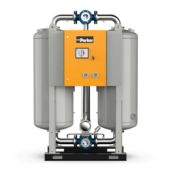
Technical product description Summary drawing Front view Main outlet valve l Pressure transducer Control air filter and pressure reducer Vessel Filler sleeve for desiccant Dew point measuring chamber Switch cabinet with operating panel Pressure build-up valve Vessel pressure gauge Discharge sleeve for desiccant Stop valve for vessel pressure gauge Main inlet valve WVM_BASIS_EN_03—07/2016... -
Page 18: Rear View
Rear view Connector box of the heater with release Lifting eye button for the safety thermostat Resistance thermometer for regeneration gas Suction opening for regeneration gas final temperature Vacuum pump Heater Lashing eye Expansion valve with silencer Resistance thermometer for the control Regeneration gas outlet of the vacuum pump temperature of the regeneration gas WVM_BASIS_EN_03—07/2016... -
Page 19: Function
Function The dryer dries the compressed air provided by the compressor and makes it available for industrial use. Upstream filters clean the compressed air and remove dust, dirt, oil, and water droplets, before the compressed air reaches the dryer. Thus, an upstream filter is also used for extending the service life of the drying agent. - Page 20 Expansion phase (duration: some minutes) The pressure in the right vessel is released through the expansion valve until the ambient pressure is reached. The escaping of the compressed air is thereby audible at the silencer as a low hum. Expansion phase Heating phase (duration: several hours) A vacuum pump sucks ambient air through the...
- Page 21 Pressure build-up phase (duration: several minutes) After completion of the cooling phase, the pressure in the vessel is raised to operating pressure via the pressure build-up line.The vessel can now be switched from regeneration to absorption operation. Stand-by-phase (for dewpoint measurement option) The regenerated vessel remains in the stand-by phase as long as the pressure dewpoint is better than the set switch over value.
-
Page 22: Options
Options The following options are available: Pressure dewpoint control Insulation and protection against contact Adaptation for outdoor installation Auxiliary heating system, anti-freeze protection Intake socket for regeneration air Intake filter for regeneration air Loop regeneration (loop cooler) ... - Page 23 Intake socket for regeneration air A supply air duct or a supplying pipe can be flanged to the dryer by way of the intake socket to guide regeneration air to the dryer (see page 26). Intake filter for regeneration air The intake filter removes solid impurities (e.g.
- Page 24 Paint compatible variant Paint finishing systems make great demands on the compressed air purity because even the tiniest impurity can degrade the paint quality. Diminutive amounts of foreign particles containing oil and grease or solvents — in particular silicones — can result in craters, discolourations, swells or other paint impurities. Paint compatible dryers are equipped with seals and filters that are absolutely free of grease and silicone and thus ensure a high compressed air quality for painting.
-
Page 25: Transportation, Installation And Storage
Transportation, installation and storage Danger due to incorrect transportation! The dryer must be transported by authorized and qualified specialist personnel only. During transportation all applicable national regulations for accident prevention must be complied with. Otherwise there is a risk of personal injury. Warning! Risk of damaging the dryer when lifting it at the lashing eyes. -
Page 26: Transporting Dryer To Its Location Of Installation
Transporting dryer to its location of installation Requirements regarding the location of installation The general conditions at the site of installation greatly affect the operation of the dryer and the service life of the desiccant. In order to ensure long-lasting operation with minimum maintenance, the location of installation must meet the following requirements: Weather protection... - Page 27 In case of draught at the installation location as can be expected with ventilation systems, passages or similar. This applies regardless of the room temperature. Measure the draught flow rate in the vicinity of the dryer when you are in doubt. Insulate the dryer if the flow rate exceeds 0.3 m/s in the immediate vicinity of the dryer.
- Page 28 Transporting of dryer Risk of serious injury due to improper transport! The dryer may only be transported by authorised and suitably qualified technical personnel. During transport, always comply with the applicable statutory safety regulations . Otherwise, there is a risk of serious injury. Warning! Risk of damaging the dryer when lifting it at the lashing eyes.
-
Page 29: Storage
Transport by crane ► Transport the adsorption dryer in an upright position to its location of installation. Transport by crane Transport by forklift ► When using a forklift, ensure that the dryer is always in an upright position. ► Secure the dryer with screws to a pallet to ensure that it cannot tilt or fall from the forklift. - Page 30 ► Disconnect the plant from the electric mains supply and any external and supply lines. ► Cover the following inlet and outlet openings with film or similar material to protect them against contamination by dust and dirt: inlet and outlet openings for compressed air —...
-
Page 31: Installation
Installation Only authorized and qualified specialist personnel may carry out work on pipes and electrical systems. The electropneumatic switch cabinet in particular must be opened and serviced by an instructed trained electrician only. As soon as the dryer has been set up at its installation location, you can install the compressed air infeed and outlet lines and make the electrical connections. - Page 32 It is therefore vital to observe the following points: Do not allow the maximum pressure loss in the air inlet and outlet pipelines to exceed 20 mbar (e.g. maximum 10 m pipline with three bends)! The selected diameter of the air inlet and outlet pipelines must be at least two nominal widths greater than that specified by the connection flange on the vacuum pump! In order to prevent corrosion in the pipes, we recommend the use of...
-
Page 33: Installation Of Pipelines
Installation of pipelines To ensure proper operation of the dryer, its connection to the compressed air system must be free from stress. ► Prior to installation, check all incoming and outgoing compressed air lines and valves for damage or contamination. ►... -
Page 34: Connection Of Electrical Components
Connection of electrical components Beware of electrical voltage! Work on the electrical system must be entrusted to instructed, authorised electricians only. The electropneumatic switch cabinet in particular must be opened and serviced by an instructed trained electrician only. Connection to power supply The dryer components have been connected in the switch cabinet at the factory. -
Page 35: Start-Up
Start-up Warning! The dryer must be taken into operation by trained personnel only! Untrained personnel does not have the required knowledge. Such personnel might cause serious faults. Note: You can order the initial commissioning and start-up from the manufacturer and have your personnel trained by the manufacturer. For telephone number, see page 8. -
Page 36: Overview Of The Operating And Display Elements
Overview of the operating and display elements The operating panel at the switch cabinet door allows for the monitoring of the operating statuses and for the modification of settings. The display is a Touch Screen Panel. To operate, touch the elements on the screen. For further information on the operating panel and the controller's functions, please refer to the enclosed controller manual. -
Page 37: Preparation For Commissioning
Operate the dryer only within the permitted limits. Operation of the dryer under conditions for which it is not designed may lead to malfunctions. On no account should the factory settings of the control programme and the frequency converter be altered without consulting the manufacturer. ... - Page 38 Avoid abrupt pressure drop! Avoid abrupt pressure drops by all means! Too fast a pressure drop or too high flow rates can cause damage to the dryer. For this reason, make sure to open the pressure outlet valve only slowly or implement a start device in the compressed air network immediately downstream of the dryer! ►...
- Page 39 The vacuum pump direction is correct, if the fan wheel rotates in the direction of the arrow. Procedure if direction of rotation of the vacuum pump is correct ► Set main switch to position "0". ► Insert heater fuses. Procedure if direction of rotation of the vacuum pump is not correct Even short-term operation of the dryer with incorrect direction of rotation of the vacuum pump might lead to damage to the heater.
- Page 40 Commissioning of dryer ► Set main switch to position "I" ► Start dryer (see the operating manual for the controller). The unit is now fully switched on, provided that no error message is displayed. How to proceed if an error message is displayed Warning! In an emergency and in the event of safety related faults (e.
-
Page 41: Monitoring Dryer Operation
Monitoring dryer operation Notes on specific operating situations Parallel operation of several plants The standard configuration comprises one compressor and one dryer. Please contact the manufacturer if you plan a plant differing from this configuration. Part-load dryer operation The dryer provides optimum performance at high loads. This is the case if the operating parameters match or slightly fall below the specified values. -
Page 42: Shutdown And Restart Dryer
Shutdown and restart dryer In the following cases, the dryer must be fully shut down and depressurised: In the event of an emergency or malfunction For maintenance work For dismantling Risk of injury from escaping compressed air! Never remove any parts of the dryer, or manipulate the same in any way, as long as the unit is pressurised! Suddenly escaping compressed air might cause serious injuries. -
Page 43: Depressurising And Shutting Down The Dryer
Note: It is not necessary to set the main switch to position "0". The display remains on. Depressurising and shutting down the dryer You must depressurise the dryer and shut it down for: maintenance disassembly ► Stop dryer (see the operating manual for the controller). Depending on the installed controller, the following stop situations can occur: ... -
Page 44: If Work Is To Be Carried Out On The Electrical System
If work is to be carried out on the electrical system ► Depressurise and shut down the dryer, following the instructions in the above chapter. Risk of injury due to voltage-carrying parts! The electrical supply cable and external power lines are live even after the dryer is switched off and, in the event of body contact, may cause serious injury! Before carrying out any work on the electrical system, the electrical supply cable and all external power lines must be made voltage-... -
Page 45: Maintenance And Repair Of The Dryer
Maintenance and repair of the dryer In order to allow maintenance work on the dryer to be carried out efficiently and without danger for maintenance personnel, you should comply with the following instructions. Notes on maintenance Warning! Maintenance tasks may be carried out only by authorized and qualified specialist personnel, and only with the plant in a switched off and depressurised condition. -
Page 46: Regular Maintenance Tasks
Regular maintenance tasks The table below shows an overview of the regular maintenance tasks. The individual tasks are described in detail on the following pages. Maintenance interval Component Maintenance task Entire dryer Complete visual inspection and function test. Heater Inspect intake opening for regeneration gas. -
Page 47: Daily Maintenance Tasks
Electric current warning! Work on the electric system must only be carried out by qualified technical personnel! Cleaning ► Remove dust with dry cloth; use moist cloth, if necessary. ► Clean all surfaces, e.g. at the operating panel, with a moist cloth. Daily maintenance tasks Complete visual inspection and function test of the entire dryer ►... -
Page 48: Monthly Maintenance
Monthly maintenance Inspect intake opening for regeneration gas The regeneration gas is fed to the system through an intake opening at the heater. ► Wait until the dryer has reached the stand-by phase (see page 21). ► Work with care and do not touch hot surfaces: After the vacuum pump has stopped, inspect screws at the intake —... -
Page 49: Maintenance Work To Be Completed Every 12 Months
Maintenance work to be completed every 12 months Replacing the silencer The dryer is equipped with silencers. A ram pressure builds up when a silencer is blocked, which could even cause the silencer to burst. Risk posed by a blocked silencer! Dangerous excess pressure may develop at blocked silencers, causing the silencers to burst. - Page 50 ► Remove the base of the filter housing. ► Remove filter element by turning it. ► Renew filter element. ► Mount the base of the filter housing. ► Dispose of spent filter element according to the statutory regulations. ► If no other maintenance work is required: Restart dryer (see page 44).
-
Page 51: Maintenance Work To Be Completed Every 24 Months
► Take the new dewpoint sensor (2) from the box, remove the protective caps (4, 5) and screw it into the sensor chamber (3). ► Place seal onto sealing face; connect adapter (1) and secure it by tightening the screw. ►... - Page 52 Replace desiccant sieve Between vessel and upper arch pipe, desiccant sieves are fitted which retain the drying agent dust. If these desiccant sieves become blocked, a dam pressure is generated which can cause compressed air fluctuations in the compressed air system.
- Page 53 Please observe the following safety instructions when replacing the desiccant: Wear eye protection and a dust mask because of increased dust formation! Emptying the desiccant may lead to increased dust formation. Wear goggles to avoid eye irritations! Wear a dust mask to avoid inhaling the dust! Risk of slipping! Spilt desiccant beads lead to a risk of injury from slipping! Immediately remove any spilt desiccant.
- Page 54 Filling vessel with new desiccant Risk of falling! Do not use the dryer as a climbing aid. The components are not designed to bear such a load and may break. Only use approved climbing aids when filling the vessel. Note: Filling can also occur via the main line socket.
-
Page 55: Identify And Eliminate Faults
Identify and eliminate faults The following table provides information on what designatory abbreviations are to be used for the various components. These designations are also found in the technical documentation. Abbreviation Component Fittings, general Butterfly valve Check valve Cardan shaft 4/2-way tap cock Dummy plug/flange Sieve bottom/desiccant sieve/flow distributor... -
Page 56: Notes On Error Messages And Errors
Notes on error messages and errors The error message from the dryer are displayed on the operating panel. The controller manual provides appropriate information. You are given information on the possible causes for the error and tips how to eliminate the error. If the dryer is connected to a fault signalling system, all error messages are transmitted through the potential-free busbar connection to the operator's control room. -
Page 57: Index
Index Wartungsintervall ..........46 Dryer maintenance interval..........46 Address, manufacturer ..........8 Drying agent Adsorption, principle ..........19 charging ............... 22 Ambient air .............. 26 storage ..............30 Ambient temperature ..........26 Dust filter Auxiliary heating system .......... 22 maintenance interval..........46 Dust formation ........... - Page 58 permitted ..............15 abrupt ..............38 Limit values, permitted ..........37 Pressure drop Location of installation, requirements .......26 abrupt ..............38 Loop regeneration ............23 Pressure increase abrupt ..............37 Pressure transducer ..........17 pressure vessel ..........15, 45 Machine damage, prevention ........11 Machine passport ............
- Page 59 Use, safe ..............9 Vessel pressure gauge ..........17 Visual inspection ............47 Voltage ..............12 electrical .............. 34 Vacuum pump maintenance interval ........... 46 Vacuum pump ............18 Vacuum pump ............20 Warranty ..............9 Variable cycle ............22 Weather protection ..........
-
Page 60: Appendix: Technical Documents
Appendix: Technical Documents The appendix of this operating manual contains the following technical documents and data:: Technical data List of service and desiccant kits Process diagram Pneumatic diagram of the control air unit Dimension drawing ... -
Page 61: Technical Data - Overview Of Standard Dryers
Technical data – overview of standard dryers Note: For dimensions and weight of the dryer refer to the enclosed dimensional drawing! Nominal capacity* mbar WVM 40 5,55 ~136 WVM 50 5,55 ~171 WVM 65 9,70 ~207 WVM 85 9,70 ~260 WVM 120 1180 1062... - Page 62 Fill quantities Dessicant Silica gel Silica gel Bottom waterproof Silica gel waterproof Silica gel Note on load cycle calculation: According to the EC pressure equipment directive the dryers are rated for 14,000 load cycles. This corresponds to a service life of approx. 20 years when operated in the fixed cycle of 6 hours (12 h total cycle time).
-
Page 63: Spare Parts List
Spare parts list Note: When exchange or replacement parts are ordered, always state the dryer type and the build no. of the dryer. These data are found on the type plate. Service kits (wear parts kits, valid for 10 bar variants) Maintenance Order no. - Page 64 Additional spare parts For model Order no. Quantity Purchased parts package WVM 40-50 GasKIT40W Flat gasketsDN40 WVM 65-85 GasKIT50W Flat gasketsDN50 WVM 120-200 GasKIT80W Flat gasketsDN80 WVM 235-355 GasKIT100W Flat gasketsDN100 WVM 410-710 GasKIT150W Flat gasketsDN150 WVM 800-1080 GasKIT200W Flat gasketsDN200 WVM 1230-1450 GasKIT250W Flat gasketsDN250...
Need help?
Do you have a question about the WVM Series and is the answer not in the manual?
Questions and answers