Table of Contents
Advertisement
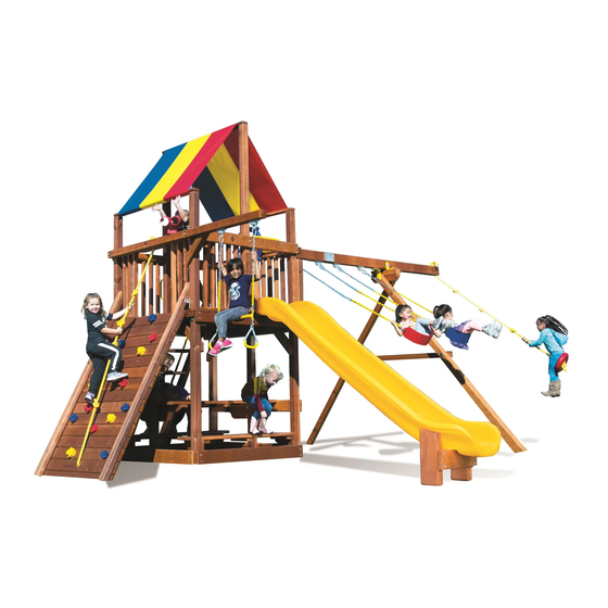
Turbo Carnival Clubhouse
Assembly Instructions
5-70-0418
(Rev 0 - 1/13/16)
Contains Assembly, Use, and Maintenance Instructions
WARNING: Not suitable for children under 36 months. Fall Hazard.
!
Only for domestic use.
To be used under the direct supervision of an adult. Intended for children ages 3-12.
This owner's manual contains important information about how to assemble, locate, use,
and maintain this playground equipment. Read this manual before you start assembly. Follow all
instructions. Be sure to educate all children who use this playground and all adult supervisors about
the rules for safe use that are contained in this manual.
Keep this Owner's Manual for future reference and to remind you of how to safely use and maintain this equipment.
RAINBOW RESERVES THE RIGHT TO MAKE CHANGES AND MODIFICATIONS TO THIS PRODUCT.
COPYRIGHT 2016 RAINBOW PLAY SYSTEMS, INC. ALL RIGHTS RESERVED
Advertisement
Table of Contents

Subscribe to Our Youtube Channel
Related Manuals for Rainbow Turbo Carnival Clubhouse


Summary of Contents for Rainbow Turbo Carnival Clubhouse
- Page 1 Keep this Owner's Manual for future reference and to remind you of how to safely use and maintain this equipment. RAINBOW RESERVES THE RIGHT TO MAKE CHANGES AND MODIFICATIONS TO THIS PRODUCT. COPYRIGHT 2016 RAINBOW PLAY SYSTEMS, INC. ALL RIGHTS RESERVED...
-
Page 2: Table Of Contents
OWNER'S MANUAL Rainbow Play Systems, Inc. Thank you for choosing Rainbow Play Systems, Inc. Please read the instruction manual thoroughly before you start building your Turbo Carnival Clubhouse to help ensure safe installation. Familiarize yourself with all hardware and parts to help with building your playground. -
Page 3: Rules For Safe Play
Rules for safe play on your play system. Do not allow children in the area while you are assembling your play system. Many of Rainbow's components are very heavy and could seriously injure a child. Observing these rules reduces the likelihood of serious or fatal injury. - Page 4 Choosing a location for your play system When selecting your play site, always keep the child's safety in mind. Here are some recommendations that should help you achieve a safe play area. 1. The play system should be located on solid level ground free of objects that could cause injury such as, but not limited to, tree stumps, roots, and large rocks.
-
Page 5: Maintenance
Maintenance of your play system To ensure safe enjoyment of your Rainbow Play System for years to come, follow these maintenance tips: 1. At the beginning of each usage season and twice each month, check and tighten as needed (but do not over tighten causing the wood to crack) all nuts and bolts. - Page 6 3. DO NOT allow children to play on the play system until it is completely assembled in a proper location. 4. DO NOT allow children in the area while you are assembling your play system. Many of the Rainbow Play Systems, Inc.
-
Page 7: Commonly Asked Questions
If play surfaces or play items become overly sticky with pitch use rubbing alcohol to safely remove. Question: What accessories may be added or what modifications can be made to my Rainbow boxed kit set? Answer: Rainbow boxed kit sets are complete kits and are not modular. Play sets with unauthorized accessories or modifications will not be covered under warranty. - Page 8 Hardware For Assembly *NOTE: Thread length may vary from what is pictured. H223...
- Page 9 Hardware For Assembly *NOTE: Thread length may vary from what is pictured. H225 H151 H123 H124 H146 H116 H100 H131 H119 H108 H104 H135 H121 H138...
- Page 10 Hardware for Assembly *NOTE: Thread length may vary from what is pictured. H176 H194 H152 H153 H125 H154 H183 H155 H196 H188 H122 H133 H164 H157 H192 H166 H216 H140 H171 H224 H139 H167 H226...
- Page 11 Hardware For Assembly H215 H222 H221 TOOLS REQUIRED FOR ASSEMBLY Tape Measure Carpenters Level Electric Impact Gun or 7/16" Deep Well Socket Carpenters Square 1/4" and 3/8" Ratchet 1/2" Deep Well Socket H174 Rubber Mallet (optional) 1/8" Drill Bit 9/16" Deep Well Socket Claw Hammer 1/4"...
- Page 12 Carnival Clubhouse Hardware List F/N# DESCRIPTION DIMENSION FOUND IN Flat Washer 1/4" 5-46-0857 Flat Washer 3/8" 60/4 5-46-0857/5-46-0411 Flat Washer 1/2" 5-46-0857 Flat Washer 3/4" 5-46-0857 Lock Washer 3/8" 10/4 5-46-0857/5-46-0411 Lock Washer 1/2" 5-46-0857 Standard Nut 1/2" 5-46-0857 Nylock Nut 3/8"...
- Page 13 2 @ SMALL 90 BRACKET 2 @ 90 BRACKET 1 @ TELESCOPE 1 @ SHIP'S WHEEL (5-35-0089) (5-35-0090) (5-41-0020) (5-41-0021) 4 @ 3/8" BOLT CUP 1 @ RAINBOW PLAQUE 6 @ GROUND STAKE 2 @ SWING HANGER (5-47-0043) (5-42-0028) (5-47-0033) (5-45-0012)
- Page 14 Turbo Carnival Clubhouse Hardware List F/N# DESCRIPTION DIMENSION FOUND IN Flat Washer 1/4" 5-46-0879 Flat Washer 3/8" 5-46-0879 Flat Washer 1/2" 5-46-0879 Flat Washer 3/4" 5-46-0879 SAE Flat Washer 1/4" 5-46-0690 Lock Washer 3/8" 5-46-0879 Lock Washer 1/2" 5-46-0879 Standard Nut 1/2"...
- Page 15 2 @ 4 x 4 x 114" 70" DH CORNER UPRIGHT (3-06-0174) 6175 2 @ 4 x 4 x 61 3/8" MAIN BEAM (3-06-0175) Turbo Carnival Clubhouse Non-Wood Parts List N156 2 @ SAFETY HANDLE 2 @ SMALL 90° BRACKET 20 @ ROCKS 2 @ 90°...
- Page 16 Carnival Clubhouse Tarp Option Parts List 3142 3 @ 2 x 4 x 58" TARP BOARD (3-03-0142) 6133 2 @ 4 x 4 x 74 5/8" CENTER POST (3-06-0133) *NOT SHOWN: 1 @ CARNIVAL CLUBHOUSE TARP N326 (5-22-0265) (5-22-0266) Carnival Clubhouse Wood Roof Hardware List F/N# DESCRIPTION DIMENSION...
- Page 17 60" DH Carnival Clubhouse Rock Wall Hardware List F/N# DESCRIPTION DIMENSION FOUND IN Flat Washer 1/4" 5-46-0858 Flat Washer 3/8" 5-46-0858 SAE Flat Washer 1/4" 5-46-0690 Lock Washer 3/8" 5-46-0858 4 Prong T-Nut 1/4" 4/16 5-46-0858/5-46-0690 4 Prong T-Nut 3/8" 5-46-0858 Carriage Bolt 1/2"...
- Page 18 Carnival Clubhouse Picnic Table Hardware List F/N# DESCRIPTION DIMENSION FOUND IN Flat Washer 3/8" 5-46-0860 H116 Lag Bolt 3/8" x 3 1/2" 5-46-0860 H155 Phillips Wood Screw #8 x 2 1/2" 5-46-0860 Carnival Clubhouse Picnic Table Parts List 3133 3146 2 @ 2 x 4 x 51 1/4"...
- Page 19 Carnival Clubhouse Lower Level Playhouse Hardware List F/N# DESCRIPTION DIMENSION FOUND IN Flat Washer 3/8" 5-46-0861 Carriage Bolt 1/2" x 8" 5-46-0861 H116 Lag Bolt 3/8" x 3 1/2" 5-46-0861 H152 Phillips Wood Screw #8 x 1 1/2" 5-46-0861 H155 Phillips Wood Screw #8 x 2 1/2"...
- Page 20 Carnival Clubhouse Upper Level Cabin Package Hardware List F/N# DESCRIPTION DIMENSION FOUND IN Flat Washer 3/8" 5-46-0862 H116 Lag Bolt 3/8" x 3 1/2" 5-46-0862 H152 Phillips Wood Screw #8 x 1 1/2" 5-46-0862 H155 Phillips Wood Screw #8 x 2 1/2" 5-46-0862 H122 Hex Head Bolt...
- Page 21 Carnival Clubhouse Sandbox Add-On Hardware List F/N# DESCRIPTION DIMENSION FOUND IN Flat Washer 3/8" 5-46-0011 H116 Lag Bolt 3/8" x 3 1/2" 5-46-0011 4920 4 @ 2 x 6 x 58" 4 HOLE FACIA (1-04-0920) Driving Panel Parts List F/N# DESCRIPTION DIMENSION FOUND IN...
- Page 22 2 @ 1 x 6 x 21 1/2" CHALKBOARD RUNNER N181 (1-02-0174) 3160 2 @ 2 x 4 x 24 3/4" CHALKBOARD SIDE (1-03-1160) 1 @ RAINBOW CHALKBOARD (5-41-0019) 3161 2 @ 2 x 4 x 15 3/8" CHALKBOARD TOP/BOTTOM (1-03-1161) Box Kit Tic Tac Toe Hardware List F/N#...
- Page 23 Double Wall Wave Slide Hardware List F/N# DESCRIPTION DIMENSION FOUND IN SAE Flat Washer 1/4" 5-46-0446 H164 Phillips Pan Head Tap Screw #14 x 1" 5-46-0446 *NOT SHOWN: 1 @ DOUBLE WALL WAVE SLIDE 5-44-0139,5-44-0140 10' Scoop Slide Hardware List F/N# DESCRIPTION DIMENSION...
- Page 24 10' Roto Wave Slide (for 70" DH) Parts List F/N# DESCRIPTION DIMENSION FOUND IN Flat Washer 3/8" 5-46-0239 Fender Washer 3/8" 5-46-0695 H104 Lag Bolt 5/16" x 2" 5-46-0695 H119 Lag Bolt 3/8" x 5" 5-46-0239 H174 Phillips Truss Head Screw #12 x 1 1/2"...
- Page 25 60" Deck Height Swing Beam Hardware List F/N# DESCRIPTION DIMENSION FOUND IN Flat Washer 1/4" 5-46-0770 Flat Washer 3/8" 11/12 5-46-0770/5-46-0410 Flat Washer 1/2" 5-46-0770 Lock Washer 3/8" 8/12 5-46-0770/5-46-0410 Standard Nut 3/8" 5-46-0770 Nylock Nut 3/8" 5-46-0410 Acorn Nut 3/8"...
- Page 26 60" Deck Height Swing Beams *NOTE: The Swing Beams shown below will be used in conjunction with the A-Frame Legs, A-Frame Blocks and non-wood parts shown on previous page. 7860 1 @ 4 x 6 x 55" 1 POSITION SWING BEAM (1-07-0860) 7849 1 @ 4 x 6 x 87"...
- Page 27 Deluxe 70" DH Swing Beam A-Frame Legs Parts List 6008 6007 1 @ 4 x 4 x 19" UPPER A-FRAME 1 @ 4 x 4 x 19" LOWER A-FRAME BRACKET BRACKET (1-06-0008) (1-06-0007) 7145 1 @ 4 x 6 x 81" A-FRAME CROSS MEMBER (1-07-0145) 7129 2 @ 4 x 6 x 131"...
- Page 28 Deluxe Swing Beams *NOTE: The Swing Beams shown below will be used in conjunction with the Deluxe A-Frame Legs, A-Frame Blocks and non-wood parts shown on previous page. 7154 1 @ 4 x 6 x 117" 2 POSITION SWING BEAM (1-07-0154) 7821 1 @ 4 x 6 x 150"...
- Page 29 Sling Swing Parts List (Per Swing) 2 @ PEAR LINK 5-47-0045 1 @ SWING SEAT (5-40-0034),(5-40-0032),(5-40-0038),(5-40-0049) N350 2 @ SWING CHAIN (5-37-0043) Half Bucket Swing Parts List 2 @ C-LINK (5-47-0044) 1 @ HALF BUCKET SWING (5-40-0046) (designed for children ages 3-5) N350 2 @ SWING CHAIN (5-37-0043)
- Page 30 Box Kit Glider Hardware List F/N# DESCRIPTION DIMENSION FOUND IN Flat Washer 1/4" 5-46-0754 Flat Washer 3/8" 5-46-0754 Flat Washer 1/2" 5-46-0754 Lock Washer 3/8" 5-46-0754 Standard Nut 3/8" 5-46-0754 Nylock Nut 3/8" 5-46-0754 Acorn Nut 3/8" 5-46-0754 Carriage Bolt 3/8"...
- Page 31 60" DH A-Frame Bench Hardware List F/N# DESCRIPTION DIMENSION FOUND IN Flat Washer 1/2" 5-46-0876 Flat Washer 3/4" 5-46-0876 Lock Washer 1/2" 5-46-0876 Standard Nut 1/2" 5-46-0876 Acorn Nut 1/2" 5-46-0876 Carriage Bolt 1/2" x 11" 5-46-0876 60" DH A-Frame Bench Parts List 6993 2 @ 4 x 4 x 70"...
- Page 32 60" Deck Height Monkey Bar Parts List Continued 7027 1 @ 4 x 6 x 86" RIGHT MONKEY BAR ARM (3-07-0027) 7028 1 @ 4 x 6 x 99 1/2" LEFT MB SUPPORT LEG (3-07-0028) 7029 1 @ 4 x 6 x 99 1/2" RIGHT MB SUPPORT LEG (3-07-0029) 6 @ 21"...
- Page 33 70" Deck Height Monkey Bar Parts List Continued 7846 1 @ 4 x 6 x 86" RIGHT MONKEY BAR ARM (1-07-0846) 7847 1 @ 4 x 6 x 109 1/2" LEFT MB SUPPORT LEG (1-07-0847) 7848 1 @ 4 x 6 x 109 1/2" RIGHT MB SUPPORT LEG (1-07-0848) 6 @ 21"...
- Page 34 Cedar Penthouse Parts List Continued 4065 3181 1 @ 2 x 6 x 23 7/8" SHORT DECK 2 @ 2 x 4 x 58" PENTHOUSE SIDE BOARD (3-03-0181) BOARD (3-04-0065) 4067 4066 1 @ 2 x 6 x 23 7/8" MONKEY BAR ENTRAPMENT BOARD 1 @ 2 x 6 x 30 5/8"...
- Page 35 Cedar Penthouse w/ Spiral Parts List Continued 3150 3146 1 @ 2 x 4 x 30 5/8" TARP FACIA 4 @ 2 x 4 x 29 1/2" SHORT RAIL UPRIGHT (1-03-1150) (1-03-1146) 3395 3143 1 @ 2 x 4 x 30 5/8" PENTHOUSE END FACIA (1-03-1143) 1 @ 2 x 4 x 30 5/8"...
- Page 36 Cedar Penthouse Wood Roof Hardware List F/N# DESCRIPTION DIMENSION FOUND IN Flat Washer 1/4" 5-46-0866 Flat Washer 3/8" 5-46-0866 Lock Washer 3/8" 5-46-0866 4 Prong T-Nut 3/8" 5-46-0866 Lag Bolt 1/4" x 3" 5-46-0866 H100 Lag Bolt 1/4" x 4 1/2" 5-46-0866 H131 Hex Head Bolt...
- Page 37 Fire Pole Parts List F/N# DESCRIPTION DIMENSION FOUND IN Flat Washer 3/8" 5-46-0880 Lock Washer 3/8" 5-46-0880 4 Prong T-Nut 3/8" 5-46-0880 H116 Lag Bolt 3/8" x 3 1/2" 5-46-0880 H123 Hex Head Bolt 3/8" x 1 1/4" 5-46-0880 H125 Hex Head Bolt 3/8"...
- Page 38 70" Deck Height Swing Options F/N# DESCRIPTION DIMENSION FOUND IN N211 Sling Swing w/72" Chain Loose Bucket Swing w/72" Chain Loose N336 Trapeze/Ring Combo w/26" Chain Loose 24" Dia. Spiral Slide Parts List (for 70" DH Clubhouse) F/N# DESCRIPTION DIMENSION FOUND IN Flat Washer 1/4"...
-
Page 41: Hardware
Step 1 First Wall Assembly *NOTE: Pre-drill 1/4" holes for all 3/8" Lag Bolts. 1. Using a hammer, pound 3/8" T-Nuts (H34) into bottom holes of the Corner Uprights (6173) (6174) and attach 4 Hole Facia (4050) through bottom holes only using 3/8" Hardware (H3) (H11) (H34) (H131). Ends and bottom of 4 Hole Facia (4050) must be flush with Corner Uprights (6129) when properly installed. - Page 42 Step 2 First Wall Assembly (continued) *NOTE: Pre-drill 1/4" holes for all 3/8" Lag Bolts. 1. Attach Rock Wall Mounting Facia (4053) to Corner Uprights (6173) (6174) through bottom pre-drilled holes in Rock Wall Facia (4053) and Main Beam (6175) using 3/4" Hardware (H5) and 1/2" Hardware (H4) (H12) (H18) (H29) (H74).
- Page 43 Step 3 Second Wall Assembly *NOTE: Pre-drill 1/4" holes for all 3/8" Lag Bolts. 1. Begin second Wall Assembly by using a hammer to pound 3/8" T-Nuts (H34) into bottom holes in Corner Uprights (6173) (6174). Attach 4 Hole Facia (4050) to Corner Uprights (6173) (6174) using 3/8" Hardware (H3) (H11) (H34) (H131).
- Page 44 Step 4 Wall Support Assembly 1. Using a hammer, pound 3/8" T-Nuts (H34) into the bottom holes in the Corner Uprights (6173) (as shown in Inset B). Stand up both wall assemblies and attach 4 Hole Facia (4050) using 3/8 Hardware (H3) (H11) (H34) (H131).
- Page 45 Step 5 Lower Level Wall Assembly 1. Position Corner Uprights (6129) against Corner Uprights (6174), lining up middle holes in Corner Uprights with previously installed 3/4" Hardware (H78). 2. Position Main Beam (6132) against Corner Uprights (6129), with counter bored holes facing out, lining up holes with previously installed 3/4"...
- Page 46 Step 6 Lower Level Wall Assembly 1. Using a 9/16" drill bit, match drill through counter bored holes in Uprights (6174), through Uprights (6129). *NOTE: Be sure prior to match drilling, outside faces of Uprights (6129) (6174) are flush. *NOTE: If installing "Double Deep" sandbox under lower level side of set, a 1 1/2" diameter counter bore, 1 1/16"...
- Page 47 Step 7 Lower Level Wall Assembly 1. Pound 3/8" T-Nuts (H34) into bottom holes in backs of Corner Uprights (6129). Attach 4 Hole Facia (4050) to Corner Uprights (6129) using 3/8" Hardware (H3) (H11) (H34) (H131). Insert 3/8" Hardware in bottom holes only. Ends and bottom of 4 Hole Facia (4050) must be flush with Corner Uprights (6129) and facia must be oriented as shown with offset holes up, when properly installed.
- Page 48 Step 8 Lower Level Wall Assembly 1. Pound 3/8" T-Nuts (H34) into bottom holes in backs of Corner Uprights (6129). Attach 4 Hole Facias (4050) to Corner Uprights (6129) using 3/8" Hardware (H3) (H11) (H34) (H131). Insert 3/8" Hardware in bottom holes only. Ends and bottom of 4 Hole Facia (4050) must be flush with Corner Uprights (6129) when properly installed.
- Page 49 Step 9 Lower Level Wall Assembly *NOTE: Depending on your set configuration, the Accessory Arm (6134) may need to be cut down. Refer to Inset A for modification instructions. 1. Measure up 85 5/8" and attach 6 Hole Facia (4051) to Corner Uprights (6129) using 3/8" Hardware (H3) (H116).
- Page 50 Step 10 Run Through Facia & Double Deep Sandbox Installation 1. On Top Joist with Swing Holes (6131) side of set, position 4 Hole Facias (4050) against Uprights (6173) (6174) (6129), up 28 1/4" from bottom of Uprights. Attach 4 Hole Facias using 3/8" Hardware (H3) (H116).
- Page 51 Step 11 Picnic Table Installation *NOTE: If not installing Picnic Table, skip to Step 13. 1. Measure up 14" from bottom of Corner Uprights (6129) and attach 4 Hole Facias (4050) to Corner Uprights (6173) (6174) using 3/8" Hardware (H3) (H116). *NOTE: 4 Hole Facias (4050) must run in the same direction as the Main Beams (6175).
- Page 52 Step 12 Picnic Table Installation 1. Measure up from bottoms of Corner Uprights (6173) (6174) 25" and attach 4 Hole Facias (4050) to Corner Uprights (6173) (6174) using 3/8" Hardware (H3) (H116). 2. Layout and attach Picnic Table Boards (4054) to 4 Hole Facias (4050) using #8 Hardware (H155). *NOTE: Picnic Table Boards (4054) should overhang 4 Hole Facias 2 7/8"...
-
Page 53: Instructions
Step 13 Deck Installation 1. Layout and evenly space Deck Boards (3140) (3144) (4052) across Main Beams (6132) (6175) referring to pattern shown below. Attach Deck Boards to Main Beams using #8 Hardware (H155). *NOTE: Deck Boards (3140) (3144) (4052) must be flush with faces of Corner Uprights (6129) (6173) (6174) when properly installed. - Page 54 Step 13 Deck Installation TOP JOIST REMOVED FOR CLARITY OF VIEW Continued from previous page: IF INSTALLING TARP OPTION, DO NOT INSERT SCREW HERE 4052 3140 H155 3144 3140 4052 6132 H155 3140 H155 6175 4050 3141 4050 3203 DO NOT INSTALL SCREW 3144 H155 3140...
- Page 55 Step 14 Facia Installation 1. Position 6 hole Facia (4051) against Corner Uprights (6174), 1 1/2" up from tops of Corner Uprights (6129) and attach using 3/8" Hardware (H3) (H116). *NOTE: If installing Wood Roof, position 6 Hole Facia (4051) directly on top of Corner Uprights (6129) (as shown).
- Page 56 Step 15 Facia Installation 1. In one 2 Hole Facia (3143), drill a 7/16" diameter hole with a 1 1/8" diameter counter bore, 3/8" deep, referring to Inset A for hole location. *NOTE: Depending on your set configuration, Corner Facias (3139) may be flipped to opposite Upright.
- Page 57 Step 16 Center Post Installation 1. If one or both of the 2 Hole Facias (3139) were not installed in Step 15, a 7/16" DIA. hole with a 1 1/8" DIA., 3/8" deep counter bore will have to be drilled in the Deck Runner (3141) (3203), as shown in Inset B.
- Page 58 Step 16 Center Post Installation INSET B 1 5/8" Continued from previous page: 1 7/16" 7/16" DIA. HOLE W/ 1 1/8" 3141 DIA. COUNTER BORE; 3/8" DEEP 1 5/8" 1 7/16" 3203 *ONLY DRILL HOLE IF 2 HOLE FACIA (3139) WAS NOT INSTALLED IN STEP 15 UNDERSIDE OF UPPER LEVEL DECK...
- Page 59 Step 17 Safety Handle Installation 1. Lay Rail Uprights w/ Handle Holes (3138) on a flat surface. Install 1/4" Hardware (H32) into pre-drilled holes (as shown). A small hammer or mallet may be used if necessary. 2. Flip Rail Uprights w/ Handle Holes (3138) and attach Safety Handles (N5) (as shown) using 1/4" Hardware (H192) and previously installed 1/4"...
- Page 60 Step 18 Rail Upright Installation *NOTE: If installing the Cabin package on Upper Level, do not install Rail Uprights (3137) (3138) on Upper Level at this time. *NOTE: When evenly spacing Rail Uprights (3137) across Top Joist w/ Swing Holes (6131) and 4 Hole Facia (4050), spacing between Rail Uprights will be approximately 2 13/16".
- Page 61 Step 19 Rock Wall & Step Ladder T-Nut Installation *NOTE: Do not fully tighten 3/8" Hardware (H124) in this step. 1. Position Ladder Legs (4045) (4046) and Rock Wall Legs (3201) as shown and install 3/8" Hardware (H34) into pre-drilled holes. A small hammer or mallet may be used to gently tap hardware flush with the wood.
- Page 62 Step 20 Step Ladder Assembly 1. Place Left Ladder Leg (4045) and Right Ladder Leg (4046) on a flat surface with the ends flush. Attach Ladder Steps (4017) to Ladder Legs (4045) (4046) using #8 Hardware (H155). 2. Attach Ladder Entrapment Board (3136) to the BACK side of Ladder, approximately 5 1/2" down, using #8 Hardware (H155).
- Page 63 Step 21 Rock Wall Assembly *NOTE: Rock Wall should be assembled on a flat surface. 1. Position Rock Wall Legs (3201) on a flat surface 42" apart from outside face to outside face, with angle cuts facing up and previously installed Brackets facing out. Make sure ends of Rock Wall Legs are flush.
- Page 64 Step 22 Step Ladder Installation *NOTE: Depending on your set configuration, it is possible to mount the ladder one opening to the right. Use the same processes shown. 1. Center Ladder Assembly between Corner Upright (6129) and Center Post (6133) (6140). 2.
- Page 65 Step 23 Rock Wall Installation 1. Position assembled Rock Wall against Rock Wall Mounting Facia (4053). Ensure Rock Wall is centered in opening and attach to Rock Wall Mounting Facia (4053) using #14 Hardware (H164) (as shown in Detail A). *NOTE: Top Rock Wall Board must be pushed up tight to Rock Wall Mounting Facia when properly installed.
- Page 66 Step 24 90 Bracket Installation 1. Position 90 Brackets (N8) on underside of Deck Runners (3141) (3203), up against 4 Hole Facias (4050). Attach Brackets to Runners and Facias using #14 Hardware (H164) (as shown in Detail A). *NOTE: If Center Posts (6133) (6140) were attached through Deck Runners (3141) (3203), 90 Brackets will have to be offset on Runners to avoid previously drilled counter bored holes.
- Page 67 Step 25 11' Scoop Slide Installation 1. Attach Slide Rails (3984) to Slide (N87) using 3/8" Hardware (H3) (H11) (H21) (H28) (H46) in locations shown. 2. Attach Slide Brace (7091) to the front of both Slide Legs (7006) (7007) using 3/8" Hardware (H3) (H116).
- Page 68 Step 25 11' Scoop Slide Installation Continued from previous page 6173 6952 H119 6133 H174 6140 SLIDE BLOCK MUST BE 3984 POSITIONED AS SHOWN 6952 HARDWARE IS TYPICAL FOR BOTH SIDES 3984 7007 7006 7091 7" H116...
- Page 69 Step 26 Roto Wave Slide Installation 1. Position Roto Wave Slide Block (6895) on inside of the Roto Wave Slide (N177), flush with the bottom of the slide, and attach through slide using 3/8" Hardware (H13) and 5/16" Hardware (H104). 2.
- Page 70 Step 27 Double Wall Wave Slide Installation *NOTE: Double Wave Slide (N24) can only be mounted on the Lower Deck. 1. Center Double Wall Wave Slide (N24) in opening, down on Deck, and attach using 1/4" Hardware (H7) and #14 Hardware (H164) (as shown in Detail A). *NOTE: Double Wall Wave Slide will sit approximately 5"...
-
Page 71: H124
(H11) (H24) (H28) (H135) and 3/8" Bolt Cup (N29). *SUGGESTION: Use a box wrench to hold on to Hex Head Bolts (H135). 2. Position Rainbow Plaque (N83) in the approximate position shown and attach to Swing Beam using #10 Hardware (H157) (as shown in Detail A). -
Page 72: H116
Step 28 Swing Beam Installation DOUBLE Continued from previous page: KNOT 7085 7084 H157 SINGLE KNOT 6131 DETAIL A DOUBLE N92 N91 KNOT H135 7085 7084 7821 7154 H116 6008 6007 H119 H151 7145 7129... - Page 73 Step 29 Ships Wheel & Telescope Installation *NOTE: Do not over-tighten hardware. Ship's Wheel (N20) and Telescope Base (N19) should rotate freely. *NOTE: Pre-drill 1/8" holes for lag bolts in this Step. 1. Center Ship's Wheel (N20) on the end of the Swing Beam and attach using hardware provided in the Ship's Wheel bag.
- Page 74 Step 30 Tarpeze Assembly *NOTE: The trapeze may need to be assembled as shown below. 1. Open C-Links (N30). *NOTE: When closing C-Links, securely tighten using a Crescent wrench. 2. Attach two Short Chains (N323) to Trapeze Bar (N18) using C-Links (N30) (as shown in Inset A). 3.
-
Page 75: H131
Step 31 Swing Hanger Installation 1. Attach Swing Hangers (N26) to Accessory Arm (6134) using 3/8" Hardware (H3) (H11) (H24) (H28) (H131) and 3/8" Bolt Cups (N29). 2. Attach Spring Clips (N27) to Swing Hangers (N26). 3. Connect previously assembled Trapeze Swing to Spring Clips (N27). H131 6134... - Page 76 Step 32 Tarp Board Installation *NOTE: If installing Wood Roof option, skip to Step 34. 1. Position Tarp Boards (3142) on top of Corner Uprights (6129) (6173) (6174) and Center Posts (6133), in locations shown below. Attach Tarp Boards using 1/4" Hardware (H1) (H97). *NOTE: Prior to installing Tarp Board (3142) on top of Corner Uprights (6129) (as shown below), install Snap Screws (H183) and Tarp (N326) on Tarp Board (3142), using processes shown on next page.
- Page 77 Step 33 Tarp Installation *NOTE: Snap Screws (H183) are rolled up in the Tarps. 1. Evenly spread Tarps (N326) over the top of the top Tarp Boards (3142). Female ends of the tarp snaps should face in towards each other when the tarp is freely hanging. 2.
-
Page 78: H152
Step 34 Wood Roof Installation *SUGGESTION: Have a helper hold Roof Supports (3156) (3157) in place. 1. Install 3/8" Hardware (H34) into pre-drilled holes of Corner Posts (6129) (6173) (6174) and into the center holes in the back of 6 Hole Facia (4051) (as shown in Details A & B), by gently tapping with a hammer until flush with face of wood. -
Page 79: H155
Step 35 Wood Roof Installation 1. Position Roof Boards (1234) on Roof Supports (3156) (3157) (as shown). Center Roof Boards (1234) on Roof Supports (3156) (3157). Starting at the top, attach Roof Boards using #8 Hardware (H152). *NOTE: The Roof Boards (1234) should be positioned so there is no gap at the peak (as shown in Inset A) and the outside edge should be flush with Peak Facia (0080) (as shown). - Page 80 Step 35 Wood Roof Installation Continued from previous page: INSET B 3157 1228 INSET A 1229 NO GAP 1229 1234 1234 1231 3156 0080 1231 3157 3156 H152 USE THE CUT DOWN ROOF 1234 RUNNER (3158) UNDER THIS SIDE ROOF BOARDS REMOVED H152 FOR CLARITY OF VIEW 1234...
- Page 81 Step 36 Ground Stake Installation *WARNING: ALL UNDERGROUND UTILITIES MUST BE LOCATED BEFORE ANCHORING PLAYSET. *NOTE: Pre-drill 1/8" holes for all 1/4" Lag Bolts. 1. Drive Stakes (N28) into the ground (in locations shown) and attach to Corner Uprights (6129) (6173) and Swing Beam A-Frame Legs (7129) using 1/4"...
- Page 82 Step 37 60" Deck Height Monkey Bar Assembly *NOTE: The 60" Deck Height Monkey Bar can only be mounted on the lower level. 1. Place Left and Right Monkey Bar Arms (7026) (7027) on a flat surface directly across from each other, oriented with counter bored holes facing up as shown.
- Page 83 Step 38 70" Deck Height Monkey Bar Assembly 1. Place Left and Right Monkey Bar Arms (7845) (7846) on a flat surface directly across from each other, oriented with counter bored holes facing up as shown. 2. Insert Pipes (N3) into pipe holes in both Monkey Bar Arms (7845) (7846) to connect the two Monkey Bar Arms (7845) (7846) together.
- Page 84 Step 39 70" Deck Height Monkey Bar Installation *NOTE: If installing Monkey Bar on the 60" Deck Height, skip to next Step. *NOTE: A Helper will be needed to complete this Step. *NOTE: Rail Uprights (3137) should not have been installed in the opening that the Monkey Bar is being installed in.
- Page 85 Step 39 70" Deck Height Monkey Bar Installation Continued from previous page: 6140 6173 6133 4051 1 11/16" 1 11/16" 6140 9/16” DIAMETER HOLES 6133 6173 COUNTER BORED HOLES IN MONKEY BAR UP INSET A 7846 H116 7845 7843 7844 ADJOINING FACES OF BRACKETS, MONKEY BAR &...
- Page 86 Step 40 60" Deck Height Monkey Bar Installation *NOTE: A Helper will be needed to complete this Step. *NOTE: Rail Uprights (3137) should not have been installed in the opening that the Monkey Bar is being installed in. If Rail Uprights were installed, remove and reinstall after Monkey Bar has been installed.
- Page 87 Step 40 60" Deck Height Monkey Bar Installation Continued from previous page: 22 3/16" 6134 1 11/16" 9/16" DIA. HOLES 6134 COUNTER BORED HOLE UP 7027 20 1/2" INSET A H116 7026 HOLE IN MONKEY 7024 7025 H116 BOTTOM HOLE IN SUPPORT H167 ADJOINING FACES OF...
- Page 88 Step 41 Slim Bracket & Rail Upright Installation *NOTE: At this point, the 60" and 70" Deck Height Monkey Bars will use the same processes unless otherwise noted. 1. Push Slim Brackets (6144) (6145) (6395) (6396) up tight to Monkey Bar, Upright (6173) and Slide Block (6952).
-
Page 89: H133
Step 42 Chin Up Bar Installation *NOTE: Depending on set configuration, Chin Up Bar may be mounted on either Monkey Bar arm. 1. Hold Chin Up Bar (N380) on underside of Monkey Bar in approximate location shown. Make a mark in center of both holes in Chin Up Bar. - Page 90 Step 43 Penthouse Assembly *NOTE: Processes for mounting the Penthouse will be the same for both the 60" & 70" Deck Height Monkey Bars unless otherwise noted. *NOTE: Processes are shown for both Tarp and Wood Roof versions. *NOTE: Processes will be the same if installing the Spiral Slide, unless otherwise noted. The Penthouse with Spiral Slide can only be mounted on the 60"...
- Page 91 Step 43 Penthouse Assembly Continued from previous page: H215 IF INSTALLING TARP VERSION INSET A H119 30 5/8" 6996 6146 3177 8 5/8" 3146 1" 8 5/8" 3146 6148 3177 6142 6932 DETAIL A 6148 6932 6995 IF INSTALLING WOOD ROOF VERSION FILLER BOARDS (6146)(6996) INSET B (6142)(6995) MAY NEED TO...
- Page 92 Step 44 Penthouse Installation *NOTE: If installing Penthouse on the 60" Deck Height Monkey Bar, skip to next Step. *NOTE: A helper will be needed for this Step, as well as the Steps moving forward. *NOTE: If installing Penthouse with Wood Roof, skip to Step 46. 1.
- Page 93 Step 45 60" Deck Height Penthouse Installation *NOTE: A helper will be needed for this Step, as well as the Steps moving forward. *NOTE: If installing Penthouse with Wood Roof, skip to Step 47. 1. With the aid of a helper, hold the first Penthouse end with the attached Filler Blocks (6142) (6995) (6146) (6996), up 2"...
- Page 94 Step 46 Penthouse Installation (Wood Roof) *NOTE: If installing Penthouse on the 60" Deck Height Monkey Bar, skip to next Step. *NOTE: A helper will be needed for this Step, as well as the Steps moving forward. 1. With the aid of a helper, hold the first Penthouse end with the attached Filler Blocks (6142) (6995) (6149), up 2"...
- Page 95 Step 47 60" Deck Height Penthouse Installation (Wood Roof) *NOTE: A helper will be needed for this Step, as well as the Steps moving forward. 1. With the aid of a helper, hold the first Penthouse end with the attached Filler Blocks (6142) (6995) (6149), up 2"...
- Page 96 Step 48 Penthouse Deck Board Installation *NOTE: Installation of Deck Boards is shown on the Tarp Version, the installation processes will be the same for the Wood Roof Version. 1. Layout and equally space Deck Boards (3174) (3395) (3179) (3394) (4065) (4017) (4068) (4019) on top of Monkey Bar, in between Penthouse Corner Posts (6148) (6932), referring to Top View of Penthouse.
- Page 97 Step 49 Penthouse Side Board Installation *NOTE: Installation processes are shown with the Tarp Version, the Wood Roof will use the same processes unless otherwise noted. *NOTE: If installing Spiral Slide, only install Penthouse Side Boards (3181) (3397) (4069) (4020) on one side, opposite the side the Spiral Slide is being mounted on.
- Page 98 Step 50 Penthouse Side Board Installation (for Spiral Slide) *NOTE: Spiral Slide can only be mounted on the 60" Deck Height. *NOTE: Installation processes are shown with the Tarp Version, the Wood Roof will use the same processes unless otherwise noted. 1.
- Page 99 Step 51 Penthouse Rail Upright & Monkey Bar Entrapment Board Installation *NOTE: Installation is shown on the Tarp Version, the Wood Roof Version will use the same processes. 1. Evenly space Penthouse Rail Uprights (3176) (3150) across Tarp Facia (4067) (4937) and Penthouse End Facia (3178) (3143).
- Page 100 Step 52 Safety Handle & Step Block Installation 1. Position Safety Handles (N5) against Penthouse Corner Post (6148) (6932) and Center Post (6138), in approximate locations shown, and attach using #14 Hardware (H167) (as shown in Inset A). 2. Hold Step Block (6143) (6696) against Rail Uprights (3137) and match drill through counter bored holes in Step Block using a 7/16"...
- Page 101 Step 53 Penthouse Center Post & Tarp Board Installation *NOTE: If installing Penthouse Wood Roof, skip to Step 55. *NOTE: Be sure to complete #'s 1-3 for both T-Brackets (N33) and Center Posts (3175). 1. Position T-Brackets (N33) against Tarp Facias (3177) (3146) (4067) (4937), lining up bottom center holes in T-Bracket with the center holes in the Tarp Facias.
- Page 102 Step 54 Tarp Installation *NOTE: Snap Screws (H183) are rolled up in the Tarps. *NOTE: Processes for installing the Tarps (N376) (N377) on the Penthouse and Penthouse with Spiral Slide will be the same. Tarp (N377) will be wrapped around top Penthouse Side Board (4020), on one side of the Penthouse.
- Page 103 Step 55 Penthouse Wood Roof Support Assembly 1. On a flat Surface, layout Roof Supports (3183) and Peak Facias (0087) (as shown below). Attach Peak Facias (0087) to Roof Supports (3183) using #8 Hardware (H154). *NOTE: Bottoms of Roof Supports must measure 30 5/8" apart when properly installed. *NOTE: Angled faces of Peak Facias must line up with faces of Roof Supports when properly installed.
- Page 104 Step 56 Penthouse Wood Roof Support Installation *NOTE: Installation processes will be the same if installing the Wood Roof on the Penthouse with Spiral Slide. 1. Position Roof Support assemblies on top of Penthouse Corner Posts (6148) (6932), 15/16" from ends of Penthouse Corner Posts (6148) (6932) (as shown in Side View of Penthouse).
- Page 105 Step 57 Roof Board Installation 1. Position Tarp Board (3180) (3396) on top of Roof Supports (3183) and Peak Facias (0087). Attach Tarp Board to Peak Facias using #8 Hardware (H155). *NOTE: Peak Facias (0087) must be 58" apart when Tarp Board is properly installed (as shown in Inset A).
- Page 106 Step 58 Spiral Slide Assembly *NOTE: Spiral Slide can only be mounted on the Penthouse on the 60" Deck Height. *NOTE: Alignment for the Left Turn Spiral Slide sections are shown on the next page. Alignment for the Right Turn Spiral Slide sections are shown page 107. For Left Turn Slide: 1.
- Page 107 Step 58 Spiral Slide Assembly (Left Turn) Continued from previous page: LONG SEAM N378 N194 LONG SEAM LONG SEAM N195 N194 SHORT SEAM DETAIL A H123 N196...
- Page 108 Step 58 Spiral Slide Assembly (Right Turn) Continued from page 105: N378 LONG SEAM LONG SEAM N194 N194 DETAIL A N379 H123 SHORT SEAM N196...
- Page 109 Step 59 Spiral Slide Installation *NOTE: Spiral Slide can only be mounted on Penthouse mounted on the on 60" Deck Height. 1. Position Spiral Filler Board (7854) directly under Penthouse Deck, pushed up tight against Penthouse Corner Post (6932) (as shown in Inset A). Attach Filler Board to Monkey Bar using 3/8"...
- Page 110 Step 60 Cabin Facia Installation *NOTE: If installing Cabin Package, Short Center Post (6140) should have been modified (as shown in Inset A). 1. Attach 3/8" Hardware (H3) (H11) (H34) (H122) in top hole of 6 Hole Facia (4051) (as shown in Inset B).
- Page 111 Step 61 Cabin Upright Installation 1. Evenly space Rail Uprights (3137) (4073) between Corner Uprights (6173) (6174), across Top Joist (6131) and 2 Hole Facia (3143). Attach Rail Uprights using #8 Hardware (H155). 2. Position Cabin Uprights (1243) directly on top of Rail Uprights (3137), pushed up tight to each other and Corner Posts (6173) (6174).
- Page 112 Step 62 Cabin Upright Installation 1. Evenly space Rail Uprights (3137) (4073) across 6 Hole Facia (4051) and 2 Hole Facia (3139). Attach Rail Uprights using #8 Hardware (H155). *NOTE: If Monkey Bar is installed leave out a qty. of two Rail Uprights (3137) and push remaining Rail Uprights up tight to Monkey Bar.
- Page 113 Step 63 Bubble Window Installation 1. On a flat surface lay out Bubble Window Frames (3214) and insert Small Bubble Panel (N168) in notches in Bubble Window Frames (3214) (as shown in Inset A). 2. Line up the corners of the Bubble Window Frames (3214) and attach together using #8 Hardware (H154).
- Page 114 Step 64 Tic Tac Toe Installation 1. Insert the three Tic Tac Toe Rods (N174) into the Tic Tac Toe Bottom (4963) (as shown in Inset A). 2. Continue Tic Tac Toe assembly by placing three Tic Tac Toe Cylinders (N172) on the Tic Tac Toe Rods (N174) followed by a Tic Tac Toe Spacer (N173).
- Page 115 Step 65 Chalkboard Assembly & Installation 1. Position Chalkboard Top/Bottoms (3161) and Chalkboard Sides (3160) around Chalkboard (N181), and slide Chalkboard into the grooves in Chalkboard Top/Bottoms (3161) and Chalkboard Sides (3160). *NOTE: Be sure that Chalkboard is oriented as shown and fits snugly, without gaps, inside Chalkboard Top/Bottoms and Chalkboard Sides.
- Page 116 Step 66 Ramp Assembly *NOTE: For ease of assembly, construct Ramp on a flat level surface. 1. Lay Ramp Boards with Holes (4027) on ground with the routered holes facing up. 2. Position Ramp Rails (3404) against Ramp Boards with Holes (4027), with counter bored holes facing in, and attach using #8 Hardware (H155).
- Page 117 Step 67 Ramp Installation 1. On back side of Accessory Arm (6134) center and attach Ramp Rope Block (6005) using 3/8" Hardware (H3) (H119) (as shown in Inset A). 2. Position assembled Ramp in opening and attach to Uprights using 3/8" Hardware (H3) (H116). *NOTE: Top of Ramp Boards (4027) (4029) must be flush with Deck (as shown).
- Page 118 Step 68 Driving Panel Assembly *NOTE: All Hardware used in these steps will be included in the Driving Panel bag. 1. Attach Steering Wheel to Driving Panel using Hex Head Bolt, Washers and Nut provided in Driving Panel bag. 2. Snap Steering Wheel Cap into Steering Wheel. DRIVING PANEL STEERING...
- Page 119 Step 70 Wacky Sign Board Installation *NOTE: Wacky Sign Boards may be positioned and attached anywhere on set as long as there is enough room to properly attach boards. 1. Position Wacky Sign Boards (1225) (1226) (1229) (1230) against the Uprights that they are being attached to and make marks for a Qty.
- Page 120 Step 71 Fire Pole Installation *WARNING: LOCATE ALL UNDERGROUND UTILITIES BEFORE DIGGING. 1. Measure out from set 19 3/4", and in from Upright 12", and dig a hole approximately 14" deep for Fire Pole assembly to sit in (as shown in Top View of Set). 2.
- Page 121 Step 72 Coil Climber Installation *WARNING: LOCATE ALL UNDERGROUND UTILITIES BEFORE DIGGING. 1. Measure out from set 19 3/4", and in from Upright 12", and dig a hole approximately 14" deep for Coil Climber assembly to sit in (as shown in Top View of Set). 2.
- Page 122 Step 73 Dual Attach Swing Beam Installation *NOTE: Processes will be the same for both the 2 Position (7856) and 3 Position (7857) Dual Attach Swing Beams. *NOTE: Position sets so that Top Joists measure 98 5/8" apart for the 3 Position Swing Beam, and 66 5/8"...
- Page 123 Step 73 Dual Attach Swing Beam Installation Continued from previous page: H225 H121 INSET A INSET B DRILL THROUGH H116 THIS HOLE USING A 9/16" DRILL BIT H116 H121 6131 6117 7856 7855 7857 CLUBHOUSE SIDE CASTLE H135 SIDE 98 5/8" H157 7857 7856...
- Page 124 Step 74 Alternate Penthouse Assembly *NOTE: Use this page in conjunction with Page 89. 1. If installing a Penthouse with a Tarp on a set with a Wood Roof, Filler Block (6146) will have to be modified. 2. Measure over 9 3/8" on Filler Block (6146) and cut Block. Router and Stain cut end. 3.
- Page 125 Step 75 Spiral Slide Assembly (for mounting on base unit) 1. Line up the long seam on the Spiral Entrance Panel (N193) with the long seam on the first 90 Elbow (N194). Rotate the 90 Elbow two holes to the left (counter clockwise) and attach using 3/8"...
- Page 126 Step 75 Spiral Slide Assembly (for mounting on base unit) Continued from previous page: N193 LONG SEAM N194 LONG SEAM LONG SEAM N195 N194 SHORT SEAM N196 DETAIL A H123...
- Page 127 Step 76 Facia & Spiral Slide Installation (for mounting on base unit) *NOTE: Spiral Slide can only be mounted to base unit off the 70" Deck Height and only on the Tarp Version. 1. Position 2 Hole Facia (3405) directly on top of 4 hole Facia (4050), flush with Corner Uprights (6173), and attach using 3/8"...
- Page 128 Step 76 Facia & Spiral Slide Installation INSTALL RAIL UPRIGHTS (3137) AS SHOWN IN STEP Continued from previous page: 6133 INSET A 18 IN THIS OPENING AFTER FACIAS ARE 6131 INSTALLED 4030 H116 6173 4030 30 7/8" H116 3405 43 5/8" 6173 4050 4030...
-
Page 129: Warranty
This warranty excludes Super Funhouse (which has its own warranty) What is covered: Subject to the limitations set forth below Rainbow Play Systems, Inc. ( “Rainbow” ) warrants, to the original retail purchaser, that the Rainbow play set (system) will be free from material defects in material and workmanship for the periods set forth below from the time of purchase, as follows: LIFETIME: Wooden components for structural failure only, due only to wood rot or insect infestation.
Need help?
Do you have a question about the Turbo Carnival Clubhouse and is the answer not in the manual?
Questions and answers