Table of Contents
Advertisement
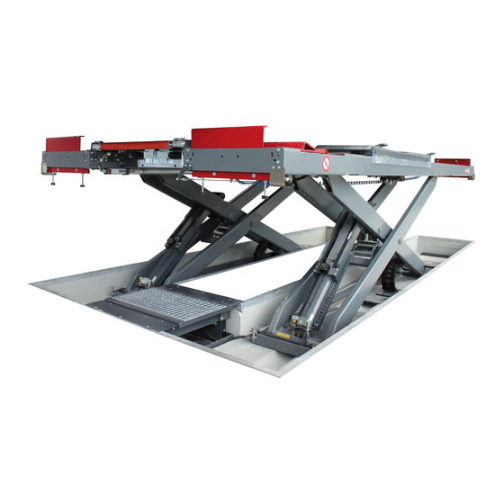
DUO CM
Scissors Lift
Original Operating Instructions
BA082901-en
Fehler! Verwenden Sie die Registerkarte 'Start', um Name dem Text zuzuweisen, der hier angezeigt werden soll.Fehler! Verwenden Sie die
Registerkarte 'Start', um Name dem Text zuzuweisen, der hier angezeigt werden soll.Fehler! Verwenden Sie die Registerkarte 'Start', um
Name dem Text zuzuweisen, der hier angezeigt werden soll.
Advertisement
Table of Contents

Related Manuals for MAHA DUO CM Series


Summary of Contents for MAHA DUO CM Series
- Page 1 DUO CM Scissors Lift Original Operating Instructions BA082901-en Fehler! Verwenden Sie die Registerkarte 'Start', um Name dem Text zuzuweisen, der hier angezeigt werden soll.Fehler! Verwenden Sie die Registerkarte 'Start', um Name dem Text zuzuweisen, der hier angezeigt werden soll.Fehler! Verwenden Sie die Registerkarte 'Start', um Name dem Text zuzuweisen, der hier angezeigt werden soll.
- Page 2 BA082901-en 2020-01-24 © MAHA Maschinenbau Haldenwang GmbH & Co. KG The reproduction, distribution and utilization of this document as well as the communication of its con- tents to others without explicit authorization is prohibited. Offenders will be held liable for the payment of damages.
-
Page 3: Table Of Contents
Contents Safety .......................... 5 Introduction ........................... 5 Symbols and Signal Words ..................... 5 1.2.1 Personal Injury ........................ 5 1.2.2 Property Damage ........................ 5 1.2.3 Information .......................... 5 Intended Use .......................... 6 Inappropriate Use ........................ 6 ... - Page 4 Routing the Manual Lowering Rope on Lifts with Power Unit in Middle Platform ..... 2 3 5.9.1 Manual Lowering Rope with 5.5 kW Unit in Middle Platform .......... 2 3 5.10 Manual Lowering of the Lift .................... 2 4 5.10.1 Important Notice Regarding Manual Lowering .............. 2 4 5.10.2 Sequence of Actions for Manual Lowering ................ 2 4 5.10.3 Identifying the Hydraulic Power Unit .................. 2 5 ...
-
Page 5: Safety
Safety Introduction Thoroughly read this manual before operating the equipment and comply with the instructions. Always display the manual in a conspicuous location. Personal injury and property damage incurred due to non-compliance with these safety instructions are not covered by the product liability regulations. Symbols and Signal Words 1.2.1 Personal Injury... -
Page 6: Intended Use
Intended Use This lift shall be used exclusively for the safe lifting of motor vehicles. Observe the rated load capacity and load distribution. The lift shall not be modified without the express written consent of the manufac- turer. In case of non-compliance the declaration of conformity becomes void. Inappropriate Use WARNING Any use other than described is inappropriate, for example:... -
Page 7: Safety Instructions For Commissioning
Safety Instructions for Commissioning WARNING The lift shall be installed and commissioned by authorised service personnel only. Use personal protective equipment. All safety features must be checked for proper function at commissioning. The control desk (if present) shall not be installed in the danger zone of the lift. ... - Page 8 Lifts with runways: modifications (such as usage of extensions) are permissible only under the condition that the functionality of the roll-off protection is maintained (protective position of ≥ 0.1 m above the runways). The load rating on the identification plate must not be exceeded. ...
-
Page 9: Safety Instructions For Servicing
Protect all parts of the electrical equipment from humidity. Use caution with operating vehicle engines. Danger of poisoning! When removing heavy vehicle components, the centre of gravity can change. In such circumstances appropriate action must be taken as required. ... -
Page 10: What To Do In The Event Of Defects Or Malfunctions
1.10 What to Do in the Event of Defects or Malfunctions WARNING In case of defects or malfunctions such as uncontrolled lift movement or defor- mation of the superstructure, support or lower the lift immediately. Turn off the main switch and secure it against unauthorized usage. Contact service. 1.11 What to Do in the Event of an Accident ... -
Page 11: Safety Features
1.12 Safety Features Dead Man's Type Control The operator is required to hold the control in the engaged position to initiate and maintain a particular operation. Roll-off Protection Once the runways are raised, the approach ramps rise and act as chocks. Longitudinal Light Barriers as Pinch Point Protection (Option) The outside edges of the runways are equipped with light barriers. -
Page 12: Description
Description General Information The lifts of this series are equipped with two runways supported by a scissors structure. The drive system consists of two hydraulic cylinders with hydraulic power unit. The lift is operated via an electric dead man's type control using pushbuttons, synchronization is achieved through a magnetostrictive measuring system. - Page 13 Raising/Lowering time, load-dependent ............ca. 50/40 s DUO CM 5.0 A: Overall dimensions (L x W x H) ......6800 x 2210 x 290 mm DUO CM 5.0 U: Overall dimensions (L x W x H) ......5200 x 2210 x 290 mm DUO CM 5.0 A: Drive-on height (w/o accessories) ..........
-
Page 14: Sample Nameplate
Sample Nameplate Lifts of this series have one large and one small nameplate each at the control desk and at the hydraulic power unit. In the event of customer complaints, hotline requests or spare parts orders, serial number and YoM of the lift should always be indicated. SCISSORS LIFT Ser. -
Page 15: Transport And Storage
Transport and Storage NOTICE Check package to ensure it is complete, in accordance with the order confirmation. Report any transport damage to the carrier immediately. During loading, unloading and transport always use suitable lifting equipment, material handling equipment (e.g. cranes, forklifts, etc.) and the right load handling attach- ments and slings. -
Page 16: Controls And Indicators
Controls and Indicators Function Short Form A Raise lift LIFT UP B Lower lift LIFT DOWN Raise wheel-free jack WFJ UP D Lower wheel-free jack WFJ DOWN Lower onto locks LOCK Hydraulic inclination (DUO CM only) G Unlock sliding plate (DUO UC only) H LED red (Malfunction or Error code) LED yellow (Warning or Error code) LED green (Ready for operation) -
Page 17: Display Codes
1 The support blocks are approved for usage on lifts with a rated load capacity of 3,500 kgs. 2 Always use four original MAHA support blocks of identical size and shape. 3 Do not use support blocks with cracks, broken-off pieces or other damage. - Page 18 The support block must be placed fully on the surface without extending byond the edges. A Extension B Support surface; available are: – Granulate coating C Support block – Granulate foil – Rubber plate BA082901-en...
- Page 19 Diagonal positioning is permissible only with granulate coated surfaces (a). If knobbly pads are used, these must mesh with the support blocks (b). BA082901-en...
-
Page 20: Stacking Two Blocks On Top Of Each Other
5.4.1 Stacking Two Blocks on Top of Each Other Only the “DUO“ hard rubber blocks (VZ 975074) and the ductile plastic blocks (VZ 970045) may be stacked on top of each other, but not more than two blocks per lifting point. -
Page 21: Lowering
Make sure to center the vehicle on the lift. Eccentric positioning may result in faulty measurement. Lowering 1 To lower the lift press the LIFT DOWN button until the desired height is reached. Lift briefly raises to disengage the latches from the mechanical locks. ... -
Page 22: Hydraulic Inclination
Hydraulic Inclination CAUTION Apply the parking brake before enabling the runway inclination! Button F2 is used for controlling the runway inclination. 5 seconds after pushing the button for the last time, the direction of movement can be changed: from "inclined position"... -
Page 23: Routing The Manual Lowering Rope On Lifts With Power Unit In Middle Platform
Routing the Manual Lowering Rope on Lifts with Power Unit in Middle Platform 5.9.1 Manual Lowering Rope with 5.5 kW Unit in Middle Platform 1 When commissioning for the first time, remove the wire rope from the lowering valve +C-M2 in direction of the pull. 2 Remove the wire rope from the middle platform at the side, and guide it below the lifting floor. -
Page 24: Manual Lowering Of The Lift
5.10 Manual Lowering of the Lift 5.10.1 Important Notice Regarding Manual Lowering WARNING Perform actions in the sequence described! The sliding shoes must only be at- tached after the seat valves have been mechanically disabled. If the lowering procedure needs to be interrupted, first remove the sliding shoes and then enable the cylinder’s seat valves. -
Page 25: Identifying The Hydraulic Power Unit
5.10.3 Identifying the Hydraulic Power Unit Version Power unit Raising/ Identification (Motor nameplate) Lowering time 2.5 kW 40 s / 50 s 5.5 kW 20 s / 30 s 2x 5.5 kW 12 s / 15 s BA082901-en... -
Page 26: Manual Lowering With 2.5 Kw Or 5.5 Kw Power Unit In The Control Desk
5.10.4 Manual Lowering with 2.5 kW or 5.5 kW Power Unit in the Control Desk 1 Open the cap of seat valve +A-M1 (by turning it anticlockwise), making sure not to lose the sealing ring. 2 Remove the coil with plug-in connector from the valve and tighten the cap (without coil) finger-tight. - Page 27 +A-M1 +B-M1 +C-M2 +C-M4.B +C-M4.A BA082901-en...
-
Page 28: Manual Lowering With 2 × 5.5 Kw Power Unit In The Control Desk
5.10.5 Manual Lowering with 2 × 5.5 kW Power Unit in the Control Desk Disengage Latch If the latch can be disengaged, continue to point “Perform Manual Lowering”. 1 Use hand pump. Raise the sides one after the other – the seat valve (+C-M5.A / +C-M5.B) on the other side must remain active in each case. - Page 29 +C-M5.B +C-M5.A +C-M4.B Hand pump +C-M4.A BA082901-en...
-
Page 30: Manual Lowering With 5.5 Kw Power Unit In The Middle Platform
5.10.6 Manual Lowering with 5.5 kW Power Unit in the Middle Platform 1 Open the cap of seat valve +A-M1 (by turning it anticlockwise), making sure not to lose the sealing ring. 2 Remove the coil with plug-in connector from the valve and tighten the cap (without coil) finger-tight. - Page 31 +A-M1 +B-M1 +C-M4.A +C-M2 +C-M4.B BA082901-en...
-
Page 32: Manual Lowering With 2 × 5.5 Kw Power Unit In The Middle Platform
5.10.7 Manual Lowering with 2 × 5.5 kW Power Unit in the Middle Platform Disengage Latch If the latch can be disengaged, continue to point “Perform Manual Lowering”. 1 Use hand pump. Raise the sides one after the other – the seat valve (+C-M5.A / +C-M5.B) on the other side must remain active in each case. - Page 33 +C-M5.A Hand pump +C-M5.B +C-M4.B +C-M4.A Stopcock Buttons BA082901-en...
-
Page 34: Manual Lowering Of The Wheel-Free Jack
5.11 Manual Lowering of the Wheel-Free Jack 5.11.1 Manual Lowering of Wheel-Free Jack with 2.5 kW or 5.5 kW Power Unit 1 Disable seat valves +A-M50 and +B-M50 (wheel-free jack cylinder). Screw in knurled screw (clockwise). 2 If excessive offset is present, use +C-M4.A or +C-M4.B to lower the higher side. 3 Use key ring to pull up release valve +C-M2 slowly. - Page 35 +B-M50.B +A-M50.A +C-M54.A / +C-M54.B BA082901-en...
-
Page 36: Manual Lowering Of Wheel-Free Jack With 2 X 5.5 Kw Power Unit In The Middle Platform
5.11.3 Manual Lowering of Wheel-Free Jack with 2 x 5.5 kW Power Unit in the Middle Platform 1 Disable seat valves +A-M50.A and +B-M50.B (wheel-free jack cylinder). Screw in knurled screw (clockwise). 2 Lower wheel-free jack. a) Open stopcock (manual lowering control unit). b) Lowering process: Targetedly pressing the buttons on the manual lowering control unit causes the bypass stop valves (+C-M54.A / +C-M54.B) to be pneumatically actuated –... - Page 37 +B-M50.B +A-M50.A Stopcock Buttons BA082901-en...
-
Page 38: Maintenance
Maintenance DANGER Risk of death or severe personal injury by electric shock Before doing any maintenance work, turn off the main switch and protect it against tampering. Maintenance Schedule Interval Maintenance items Procedure Check fluid level, top up if necessary. Check hydraulic system for leakage. -
Page 39: Replacing The Filter Element
Replacing the Filter Element The filter element of the return flow filter must be replaced as required, but at least once per year, by an authorised service technician. Care Instructions Periodically clean the equipment and treat it with a care product. ... -
Page 40: Checking The Fluid Level
Checking the Fluid Level 1 Lower lift and wheel-free jack into bottom position. 2 Check the fluid level (see label on power unit). 3 Open the filler neck and top up the reservoir. For specification and fluid quantity see label on power unit. 4 Also perform a visual check of all hydraulic pipes and hoses. -
Page 41: Wearing Parts
Wearing Parts 6.6.1 Checking the Sliding Blocks in the Base Tub Regularly check all four sliding blocks for wear (see illustration for wear limit mark). Once the wear limit is reached, the sliding blocks must be absolutely replaced. BA082901-en... -
Page 42: Greasing Points
Greasing Points 6.7.1 Lubrication Points at the Lift Periodically lubricate all pivot points using spray grease. A Cylinder Bearings Grease cylinder bearing (bottom) and piston bearing (top) through the lubricator nipples using multipurpose grease. Remove waste grease. B Scissors Pins Grease the scissors pins through the lubricator nipples using multipurpose grease. -
Page 43: Lubrication Points At Optional Accessories
6.7.2 Lubrication Points at Optional Accessories Wheel-Free Jack Clean the slide tracks in the runway (1) and in the support plate (2) and slightly lubricate with multipurpose grease. Axle Play Detector, Model PMS Using a greaser, lubricate with multipurpose grease through the lubrication nipples (accessible from bottom side). -
Page 44: Troubleshooting
Troubleshooting Error Diagnosis Remedy Main switch turned off. Turn on main switch. Power failure. Check for cause. Lift does not run. Power cord interrupted. Contact service. Fuses defective. Contact service. Motor rotation reverse. Contact service. Low fluid level. Top up reservoir. Lift does not raise. -
Page 45: Service Lifetime
Contents of the Declaration of Conformity MAHA Maschinenbau Haldenwang GmbH & Co. KG herewith declares as a manufacturer its sole responsibility to ensure that the product named hereafter meets the safety and health regulations both in design and construction required by the EC directives stated below.
Need help?
Do you have a question about the DUO CM Series and is the answer not in the manual?
Questions and answers