Table of Contents
Advertisement
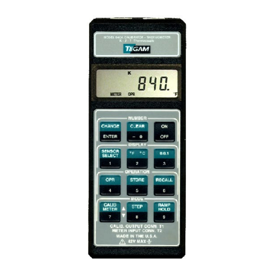
840A, 845, 850, 855
Digital Temperature Calibrator - Thermometer
MODEL 840A, 845, 850, 855
This owner's manual was as current as possible when this product was manufactured. However,
products are constantly being updated and improved. Because of this, some differences may occur
between the description in this manual and the product you received.
Instruction Manual
PN# 840A-901-01CD
Publication Date: November 2019
REV. M
10 TEGAM WAY • GENEVA, OHIO 44041 • 440-466-6100 • FAX 440-466-6110 • sales@tegam.com
Advertisement
Table of Contents

Related Manuals for Tegam 840A


Summary of Contents for Tegam 840A
- Page 1 Because of this, some differences may occur between the description in this manual and the product you received. Instruction Manual PN# 840A-901-01CD Publication Date: November 2019 REV. M 10 TEGAM WAY • GENEVA, OHIO 44041 • 440-466-6100 • FAX 440-466-6110 • sales@tegam.com...
-
Page 2: Table Of Contents
MAINTENANCE INSTRUCTIONS WITHIN THIS MANUAL ARE FOR USE BY QUALIFIED SERVICE PERSONNEL ONLY. DO NOT ATTEMPT ANY SERVICING OTHER THAN THAT CONTAINED IN THE OPERATION INSTRUCTIONS UNLESS YOU ARE QUALIFIED TO DO SO. 10 TEGAM WAY • GENEVA, OHIO 44041 • 440-466-6100 • FAX 440-466-6110 • sales@tegam.com... -
Page 3: General Information
ACCURACY: All stated accuracies are exclusive of sensor errors and lead resistance induced errors. Refer to 'UNIQUE SPECIFICATIONS' for detail accuracy specs. RESOLUTION: TEMPERATURE; 0.1 °/1° F/C OHMS; 0.01Ω/0.1Ω/1Ω 10 TEGAM WAY • GENEVA, OHIO 44041 • 440-466-6100 • FAX 440-466-6110 • sales@tegam.com... - Page 4 • Clear/-0 • Sensor Select/1 • °F/°C/2 • Resolution/3 • Operate/4 • Store/5 • Recall/6 • Calibrator/Meter/Up Ramp/7 • Calibrator Step/Down Ramp/8 • Calibrator Ramp/Meter Hold/9 10 TEGAM WAY • GENEVA, OHIO 44041 • 440-466-6100 • FAX 440-466-6110 • sales@tegam.com...
- Page 5 BATTERY LIFE, CONTINUOUS: 10 hrs. typical, alkaline; 3 hrs typical, Ni-Cd (rechargeable). BATTERY INDICATOR: Display indicates BAT when less than 10% of life remains. DIMENSIONS, WEIGHT: 7.0" x 2.9 x 1.1". Net weight 12 oz. 10 TEGAM WAY • GENEVA, OHIO 44041 • 440-466-6100 • FAX 440-466-6110 • sales@tegam.com...
-
Page 6: Unique Specifications
TEMPERATURE COEFFICIENT: From 0°C to 18°C, and 28°C to 50°C; K, J, T, E; ±(0.006% rdg + 0.03°C)/°C RTD, THERMISTOR, OHMS; ±(0.006% rdg +0.012% rng)/°C RAMP FUNCTION: Not Included. 10 TEGAM WAY • GENEVA, OHIO 44041 • 440-466-6100 • FAX 440-466-6110 • sales@tegam.com... -
Page 7: Features
Improvements or changes to this manual will be explained on an addendum included with the instrument. All change information should be incorporated immediately into the appropriate places in the manual. 10 TEGAM WAY • GENEVA, OHIO 44041 • 440-466-6100 • FAX 440-466-6110 • sales@tegam.com... -
Page 8: Unpacking And Inspection
WARNING Do not substitute a metal part for the nylon screw in the rear case. Doing so will degrade electrical isolation of the case. 10 TEGAM WAY • GENEVA, OHIO 44041 • 440-466-6100 • FAX 440-466-6110 • sales@tegam.com... - Page 9 Where the meter and calibrator connectors are simultaneously wired into a system lacking the above isolation, it is necessary to use an "ungrounded" (i.e. electrically isolated) probe at the thermometer input. 10 TEGAM WAY • GENEVA, OHIO 44041 • 440-466-6100 • FAX 440-466-6110 • sales@tegam.com...
-
Page 10: Battery Installation/Replacement
• After a new battery is installed, allow approximately 5 seconds for display turn-on the first time the unit is turned on. During this period, microcomputer initialization is performed. 10 TEGAM WAY • GENEVA, OHIO 44041 • 440-466-6100 • FAX 440-466-6110 • sales@tegam.com... -
Page 11: Memory Backup
(1) Low battery voltage, install a new battery. If problem persists, consult factory. Display reads OPEN. (1) No thermocouple, RTD or thermistor is plugged into the meter input. 10 TEGAM WAY • GENEVA, OHIO 44041 • 440-466-6100 • FAX 440-466-6110 • sales@tegam.com... - Page 12 Display reads LO. (1) Meter-mode input-temperature too low for accurate measurement. (2) Calibrator-mode keypad-entry too low for accurate simulation. Figure 2. Keypad 10 TEGAM WAY • GENEVA, OHIO 44041 • 440-466-6100 • FAX 440-466-6110 • sales@tegam.com...
-
Page 13: Initial Turn On
If the instrument is to be used as a thermometer or ohmmeter, refer to the Meter Mode Operation section for detailed instructions. For use as a temperature-calibrator or ohms simulator, refer to Calibrator Mode Operation. 10 TEGAM WAY • GENEVA, OHIO 44041 • 440-466-6100 • FAX 440-466-6110 • sales@tegam.com... -
Page 14: Meter Mode Operation (Thermocouple)
Lead resistance errors are compensated for in 3-wire configurations. However, full compensation requires equal resistance in each lead. This configuration is common with 100- ohm RTDs. 10 TEGAM WAY • GENEVA, OHIO 44041 • 440-466-6100 • FAX 440-466-6110 • sales@tegam.com... - Page 15 Any of these readouts can be recalled by turning the unit off and back (RTD, Thermistor, etc.) Figure 4. 2-Wire Resistance Measurement Figure 5. 3-Wire Resistance Measurement 10 TEGAM WAY • GENEVA, OHIO 44041 • 440-466-6100 • FAX 440-466-6110 • sales@tegam.com...
-
Page 16: Data Logging & Recall
1. While in the METER OPR mode, readings stored earlier can be displayed by first depressing the RECALL key. Note that the OPR annunciator is replaced by RCL, and all memory location 10 TEGAM WAY • GENEVA, OHIO 44041 • 440-466-6100 • FAX 440-466-6110 • sales@tegam.com... - Page 17 NOTE: There is no need to clear a location if new data is ready for saving in this location. Just STORE the new data. It will write over and delete the old. Figure 7. 10 TEGAM WAY • GENEVA, OHIO 44041 • 440-466-6100 • FAX 440-466-6110 • sales@tegam.com...
-
Page 18: Calibrator Mode Operation (Thermocouples)
To correct a numeric entry while in the NUM mode, press the CHANGE/ENTER key twice. This will return number entry to the beginning of a new number. 10 TEGAM WAY • GENEVA, OHIO 44041 • 440-466-6100 • FAX 440-466-6110 • sales@tegam.com... -
Page 19: Calibrator Mode Operation (Rtd, Thermistor, Ohms)
2. Set instrument to CALIBRATOR mode. 3. Use the sensor-select key to set the instrument to the appropriate function and range. Figure 8. 2-Wire Resistance Simulation 10 TEGAM WAY • GENEVA, OHIO 44041 • 440-466-6100 • FAX 440-466-6110 • sales@tegam.com... - Page 20 "RTD-100" (or "RTD-1000") when first selected. Thermistors are identified by a momentary alpha-numeric readout of "Y-400" (signifying YSI Series-400 type thermistor). 10 TEGAM WAY • GENEVA, OHIO 44041 • 440-466-6100 • FAX 440-466-6110 • sales@tegam.com...
-
Page 21: Storage And Recall Of Calibrator Settings
4. To return the unit to the CALIB OPR mode after recalling the last set-up, press the OPR key. NOTES: • Any other key except ON/OFF and CLEAR will also return the OPR 10 TEGAM WAY • GENEVA, OHIO 44041 • 440-466-6100 • FAX 440-466-6110 • sales@tegam.com... -
Page 22: Step Function
Whenever the battery is replaced (and memory backup is not performed), the ramp parameters default to factory-set values: 1 Step Size =10°F (K TC) 2 Start Point = 500°F 3 High Limit = 550°F 10 TEGAM WAY • GENEVA, OHIO 44041 • 440-466-6100 • FAX 440-466-6110 • sales@tegam.com... -
Page 23: Service Information
Voltage errors in these cables should be compensated at the simulator. 4. Calibration cover (820-307-4). Ambient Conditions: Units should be calibrated at an ambient temperature of 23°C ±1°C, with relative humidity less than 80%. 10 TEGAM WAY • GENEVA, OHIO 44041 • 440-466-6100 • FAX 440-466-6110 • sales@tegam.com... - Page 24 Memory locations 1 and 2 will be free for normal use. e. Set U.U.T. to METER, OPR, K, °F. f. Turn U.U.T. OFF, then ON to re-enable 'RTD' and 'Ω,' annunciators. 10 TEGAM WAY • GENEVA, OHIO 44041 • 440-466-6100 • FAX 440-466-6110 • sales@tegam.com...
- Page 25 20. Re-set U.U.T. output to 32°F, DMM reading should be 0±2μV. 21. Turn OFF U.U.T. 22. Thermocouple calibration is complete. Remove calibration cover. Reinstall original back-cover, unless going on to Part B (Resistance Calibration). 10 TEGAM WAY • GENEVA, OHIO 44041 • 440-466-6100 • FAX 440-466-6110 • sales@tegam.com...
- Page 26 Repeat steps 1 & 2 as required 0.000mV±1µV 32.0°F 0.000mV±1µV 32.0°F 0.000mV±1µV 32.0°F 0.000mV±1µV 32.0°F 1.439mV±1µV 1000.0°F 0.000mV±1µV 32.0°F 0.000mV±1µV 32.0°F 2.238mV±1µV 600.0°F 0.000mV±1µV 32.0°F 0.000mV±1µV 32.0°F *exclusive of noise 10 TEGAM WAY • GENEVA, OHIO 44041 • 440-466-6100 • FAX 440-466-6110 • sales@tegam.com...
- Page 27 SERVICE INFORMATION Figure 11. Calibration Setup, Copper Mode. Figure 12. Calibration Setup, Meter Mode. Figure 13. Calibration Setup, Calibrator Mode. 10 TEGAM WAY • GENEVA, OHIO 44041 • 440-466-6100 • FAX 440-466-6110 • sales@tegam.com...
-
Page 28: Resistance Calibration
Avoid selecting thermocouple functions while in this mode. Should it be necessary to scroll through thermocouple functions, first press the OPR key (disables flashing 'RTD'), and start again at Step 7 above. 10 TEGAM WAY • GENEVA, OHIO 44041 • 440-466-6100 • FAX 440-466-6110 • sales@tegam.com... - Page 29 SERVICE INFORMATION Figure 14. Resistance Calibration Setup 10 TEGAM WAY • GENEVA, OHIO 44041 • 440-466-6100 • FAX 440-466-6110 • sales@tegam.com...
- Page 30 32.0±0.1°F 1,000Ω 900.0Ω 900.00Ω 1,000Ω 1.00Ω √ 1.00±0.10Ω 10,000Ω 9000.0Ω 9000.0Ω 10,000Ω 10.0Ω √ 10.0±1.0Ω exclusive of noise ** adjust as necessary to obtain steps 2,5. 10 TEGAM WAY • GENEVA, OHIO 44041 • 440-466-6100 • FAX 440-466-6110 • sales@tegam.com...
- Page 31 1,000Ω 1.00Ω √ 1.00±0.20Ω 100,000Ω 90,000Ω 90,000Ω 100,000Ω 100Ω √ 100±20Ω Thermistor 47.0Ω 293.0°F Thermistor 2252Ω √ 77.0±0.2°F Thermistor 75,790Ω √ -40.0±0.2°F * exclusive of noise. 10 TEGAM WAY • GENEVA, OHIO 44041 • 440-466-6100 • FAX 440-466-6110 • sales@tegam.com...
-
Page 32: Calibration Verification
This feature is available on products that use the following (and later) software revisions: Model Software Revision 840A 4.16 Software revision is marked on a label attached to integrated-circuit U1 on the mother-board.) 10 TEGAM WAY • GENEVA, OHIO 44041 • 440-466-6100 • FAX 440-466-6110 • sales@tegam.com... - Page 33 9. Press the ENTER function button. The display will blink "Hi" once or twice and then will display "0.0 °F" blinking. There will also be an "Ω" symbol blinking in the upper left. It will blink with the "0.0 °F" display. 10 TEGAM WAY • GENEVA, OHIO 44041 • 440-466-6100 • FAX 440-466-6110 • sales@tegam.com...
- Page 34 24. Press 1 0 0 00 buttons and then press ENTER function button. "NUM" will disappear and "1000.0 °F" will appear, not blinking. The voltmeter should read 1.438 mV. 10 TEGAM WAY • GENEVA, OHIO 44041 • 440-466-6100 • FAX 440-466-6110 • sales@tegam.com...
- Page 35 U.U.T. as noted in the table. Observe the correct readings on the display of the U.U.T. 39. Select the calibrator mode by pressing the CALIB/METER function button and type “K” 10 TEGAM WAY • GENEVA, OHIO 44041 • 440-466-6100 • FAX 440-466-6110 • sales@tegam.com...
- Page 36 10. Adjust the Thermocouple Temperature Simulator to 32.0 °F. NOTE: The reading on the voltmeter should read null. 0.000 mV. Adjusting the U.U.T. to any temperature and adjusting the Temperature Simulator to 10 TEGAM WAY • GENEVA, OHIO 44041 • 440-466-6100 • FAX 440-466-6110 • sales@tegam.com...
- Page 37 16. Remove the Alloy Mode Calibrator Verification Cable from all equipment. 17. The Alloy Mode verification is now complete. Press the OFF function button to turn the unit off. 10 TEGAM WAY • GENEVA, OHIO 44041 • 440-466-6100 • FAX 440-466-6110 • sales@tegam.com...
-
Page 38: Mechanical Parts Diagram
SERVICE INFORMATION 3. MECHANICAL PARTS DIAGRAM 10 TEGAM WAY • GENEVA, OHIO 44041 • 440-466-6100 • FAX 440-466-6110 • sales@tegam.com... -
Page 39: Warranty
TEGAM service center with shipping charges prepaid. TEGAM Inc. shall pay for the return of the product to the customer if the shipment is to a location within the country in which the TEGAM service center is located. The customer shall be responsible for paying all shipping, duties, taxes, and additional costs if the product is transported to any other locations. - Page 40 The foregoing warranty of Tegam is in lieu of all other warranties, expressed or implied. Tegam specifically disclaims any implied warranties of merchantability or fitness for a particular purpose. In no event will Tegam be liable for special or consequential damages. Purchaser’s sole and exclusive remedy in the event any item fails to comply with the foregoing express warranty of Tegam shall be to return the item to Tegam;...
Need help?
Do you have a question about the 840A and is the answer not in the manual?
Questions and answers