Advertisement
Quick Links
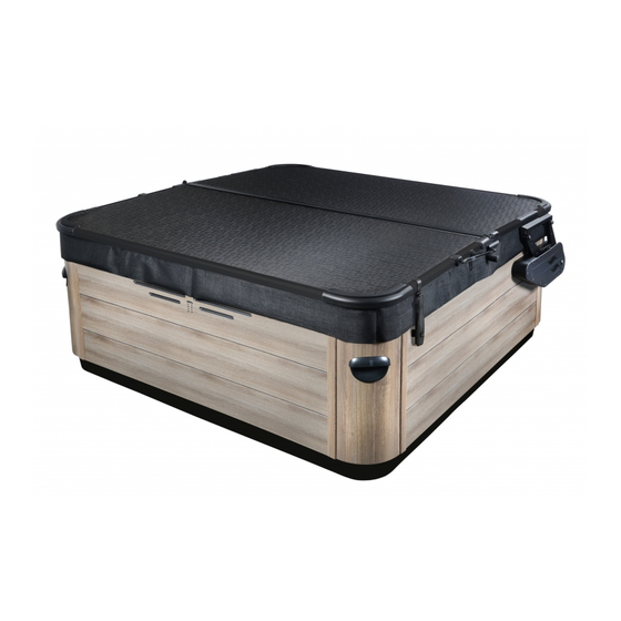
Upright 2.0
Figure 1
EAS Handle
G
Figure 2
F
Rubber
Bumper
Figure 3
Moun ng Screws
Smartop Upright 2.0 190423
EAS Bracket
Bu on Head
Socket Bolt
H
Rear Moun ng
Bracket
A
J
Installation Instructions - Updated as of 04/23/19
Step #1
Position the Smartop (in closed position) on the spa making sure that all four
corners are properly postioned and square on the spa.
Step #2
Attach the EAS handle to the EAS bracket using the supplied 5/16 x 1-1/4"
button head socket bolt (see Fig. 1).
Step #3
Slide the rear mounting bracket over the exposed tube attached to the Smartop
cover (see Fig. 2). Attach the rear mounting brackets to the rear panel on the spa
using the supplied #10 x 1-1/2" mounting screws (see Fig. 3).
Step #4
Attach the rubber bumpers to the rear mounting brackets using the supplied
#10 x 1" self-tapping screws (see Fig. 2).
Step #5
Attach the ball stud to the side mounting bracket. Next, attach the side
mounting brackets to the side of the spa, directly underneath the acrylic,
using the supplied #10 x 1-1/2" mounting screws (see Fig. 4). Note: Make sure the
center of the ball stud is 3-1/4" in from the back of the spa.
Step #6
Gently raise the Smartop into the upright position making sure to keep a firm
grip on the cover and attach the shocks to the ball studs (see Fig. 4). Note:
When attaching the shocks, make sure the body of the shock is on top.
Step #7
Attach the side tub lock cable assembly to the pre-installed tub lock bracket on
the side of the aluminum trim on the Smartop and turn the knob to lock it in
place. Next, apply downward pressure on the Smartop and mark where the
tub lock assembly needs to be attached to the spa cabinet. Unlock and remove
the side tub lock cable assembly from the tub lock bracket on the Smartop.
Attach the tub lock assembly triangle plate to the spa cabinet using the supplied
#8 x 3/4" philips flat head screws (black). Note: Do not overtighten the screws
when attaching to the spa cabinet. Swing the tub lock assembly cable up and
re-attach to the tub lock assembly bracket on the Smartop and lock it in place.
Note: Do not cover the service panel with the side tub lock assembly (see Fig. 5 & 6
for complete look).
Figure 4
L
Shock
C
Ball
Stud
B
Side
Moun ng Bracket
Page 1
Advertisement

Related Manuals for Leisure Concepts Smartop Upright 2.0


Summary of Contents for Leisure Concepts Smartop Upright 2.0
- Page 1 Note: Do not cover the service panel with the side tub lock assembly (see Fig. 5 & 6 Bumper for complete look). Figure 3 Figure 4 Shock Ball Stud Moun ng Screws Side Moun ng Bracket Smartop Upright 2.0 190423 Page 1...
- Page 2 101065 #8 X 3/4" PHILIPS FLAT HEAD SCREW (BLACK ZINC) Figure 7 101079 THERMAL SEAL CONTROL PAD 101078 LOCK Thermal Seal Control Panel Control Pad For additional information on our Smartop product, please visit our website: “www.smartopspacover.com” Smartop Upright 2.0 190423 Page 2...
Need help?
Do you have a question about the Smartop Upright 2.0 and is the answer not in the manual?
Questions and answers