Table of Contents
Advertisement
Available languages
Available languages
Quick Links
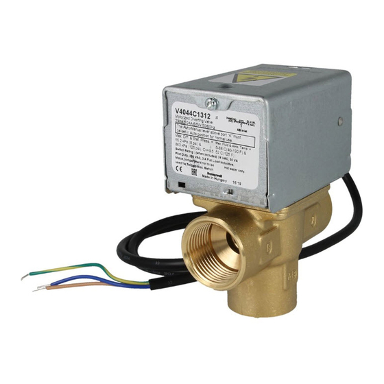
V4043, V4044, V8043 and
V8044 Zone Valves
APPLICATION
These valves consist of an actuator motor and valve
assembly for controlling the flow of hot and/or cold
water. The V4043 and V8043 provide two-position,
straight-through control of supply water. The V4044
and V8044 provide two-position, diverting control of
supply water. The valves are designed for use with fan
coil and other units requiring quiet, compact water
valves. The V8043E and F also control supply water
for baseboard radiators and convectors. The V4043E
and V8043J provide straight-through control of
steam only. Models are available with 125 or 300 psi
operating pressure.
INSTALLATION
When Installing this Product...
1. Read these instructions carefully. Failure to fol-
low them could damage the product or cause a
hazardous condition.
2. Check the ratings given in the instructions and
on the product to make sure the product is suit-
able for your application.
3. Installer must be a trained, experienced service
technician.
4. After installation is complete, check out product
operation as provided in these instructions.
CAUTION
1.
Disconnect power supply before connect-
ing wiring to prevent electrical shock of
equipment damage.
2.
Normally it is not necessary to remove the
powerhead from the valve body during
installation. If the valve must be disas-
sembled, be certain that it is reassembled
with the water flow in the direction of the
arrow. Reversal of the powerhead will
result in damage to the gear train.
3.
On 24V systems, never jumper the valve
coil terminals even temporarily. This may
burn out the heat anticipator in the ther-
mostat.
INSTALLATION INSTRUCTIONS
IMPORTANT
Use this valve in hydronic heating systems
which do not contain dissolved oxygen in the
system water. The dissolved oxygen, which is
found in systems that have a frequent source
of makeup water, causes the rubber plug
inside the valve to deteriorate and eventually
fail.
LOCATION
Install the valve in an area with adequate clearance
to:
—
Move the manual opening lever on the side of
the powerhead.
—
Remove the powerhead cover.
—
Wire the powerhead.
—
Replace the powerhead motor.
MOUNTING
The valve can be mounted in any position on a vertical
line. If the valve is mounted horizontally; the
powerhead must be even with or above the center line
of the piping. Make sure that enough room is
provided above the powerhead to remove the cover
for servicing.
HORIZONTAL
PIPING
VERTICAL
PIPING
Fig. 1. Mounting positions.
M10162A
95-6983EF-03
Advertisement
Table of Contents

Related Manuals for Honeywell Home V4043


Summary of Contents for Honeywell Home V4043
- Page 1 The dissolved oxygen, which is assembly for controlling the flow of hot and/or cold found in systems that have a frequent source water. The V4043 and V8043 provide two-position, of makeup water, causes the rubber plug straight-through control of supply water. The V4044...
- Page 2 V4043, V4044, V8043 AND V8044 ZONE VALVES Mount the valve directly in the tube or pipe. Make sure FLARE FITTING MODELS that the flow through the valve is in the direction Use new, properly reamed pipe, free from chips. The indicated by the arrow stamped on the valve body.
- Page 3 V4043, V4044, V8043 AND V8044 ZONE VALVES WIRING spring-return mechanism drives the valve to the closed position as shown in Fig. 6B. The valve can also Disconnect the power supply before connecting wiring be opened with no electrical power by moving the to prevent electrical shock or equipment damage.
- Page 4 95-6983EF—03 M.S. Rev. 11-19 | Printed in United States This product is manufactured by Resideo Technologies, Inc., Golden Valley, MN, 1-800-468-1502 ©2019 Resideo Technologies, Inc. The Honeywell Home trademark is used under license from Honeywell International Inc. All rights reserved.
- Page 5 Ces vannes sont constituées d'une vanne et d'un moteur d'actionneur pour la régulation du débit de Utiliser cette vanne dans les systèmes de l'eau chaude ou froide. Les vannes V4043 et V8043 chauffage hydronique ne contenant pas assurent une régulation de l'eau d'alimentation à...
- Page 6 VANNES DE ZONE V4043, V4044, V8043, V8044 Monter la vanne directement dans le tube ou le MODÈLES À RACCORD ÉVASÉ conduit. S'assurer que le débit par la vanne se fait Utiliser un tuyau neuf, correctement alésé et exempt dans la direction indiquée par la flèche estampée sur d'écailles.
- Page 7 VANNES DE ZONE V4043, V4044, V8043, V8044 CÂBLAGE FONCTIONNEMENT ET VÉRIFICATION Débrancher l'alimentation avant d'effectuer le câblage pour éviter les chocs électriques et les dégâts de l'équipement. Le câblage doit être conforme aux codes et aux règlements locaux. Les raccordements MISE EN GARDE aux vannes individuels sont illustrés sur les Fig.
- Page 8 95-6983EF—03 M.S. Rev. 11-19 | Imprimé aux États-Unis Ce produit est fabriqué par Resideo Technologies, Inc., Golden Valley, MN, 1-800-468-1502 ©2019 Resideo Technologies, Inc. La marque de commerce Honeywell Home est utilisée sous licence avec l’autorisation d’Honeywell International Inc. Tous droits réservés.
Need help?
Do you have a question about the V4043 and is the answer not in the manual?
Questions and answers