Table of Contents
Advertisement
Quick Links
WARNINGS AND CAUTIONS:
• TO AVOID FIRE, SHOCK, OR DEATH; TURN OFF POWER at circuit breaker or fuse and test that power is off before wiring!
• To be installed and/or used in accordance with appropriate electrical codes and regulations.
• If you are unsure about any part of these instructions, consult an electrician.
• This product is intended only for use indoors and in dry locations.
NOTES:
• For use with Leviton
®
LevNet RF™ 902 MHz products.
• It may be more convenient to link the wireless controls to the Control Transmitter prior to final installation.
DESCRIPTION
Use the Control Transmitter to wirelessly bridge control from one circuit to another.
The Control Transmitter monitors any line voltage circuit and broadcasts the status
to wirelessly control one or more circuits connected to compatible receivers. Use the
Control Transmitter with hardwired switches, occupancy sensors or light sensors to
extend the controlling capacity of the sensors beyond the wires.
FEATURES
• Easy-to-use - eliminates switch-leg runs.
• Reliable range - unique ID of each control transmitter activates only the intended
receiver(s).
• Saves energy - conserves energy and saves money by using the control
transmitter in load shedding or energy-efficient HVAC control applications;
connects HVAC, lighting, or other devices to a relay receiver to turn them OFF and
ON automatically in sync with any device connected to a control extender.
• Simple wireless control - economy HVAC controls, interlocked motor control, and
secondary circuit follows power status of primary circuit.
• Control the way you want it - controls one or multiple new devices with an
existing switch and senses power state of one device, and wirelessly controls a
receiver connected to another device.
COMPATIBLE DEVICES
• WSD05-9D0
• WSD20-9D0
• WSP20-9D0
• WSS20-G9N
• WSS20-N9N
• WSG15-D9W
• WSG15-S9W
CERTIFICATIONS
• ETL: UL 60730 (U.S.)
• ETL: CSA c22.2 no.14-05 (Canada)
• CE: IEC 60730
• ETL: UL 2043 (Plenum)
• IEC 61000-4-5 (Surge)
• FCC: SZV-STM300U (US)
• IC: 5713A-STM300U (Canada)
SPECIFICATIONS
Frequency:
902 MHz
Range:
50-150 feet (typical)
Power Input:
100-277 VAC 50/60 Hz
Power Consumption:
<0.5 W @ 120 VAC
Output:
Wireless Control Signal
Transmit EEP:
A5-3F-01, (default)
MENU button transmits Link Packet
Addressing:
Factory set unique ID
(1 of 4 Billon)
Operating Temp:
+32˚ to +122˚ F (0˚ to +50˚ C)
Storage Temp:
-4˚ to +176˚ F (-20˚ to +80˚ C)
Humidity:
10-95% non-condensing
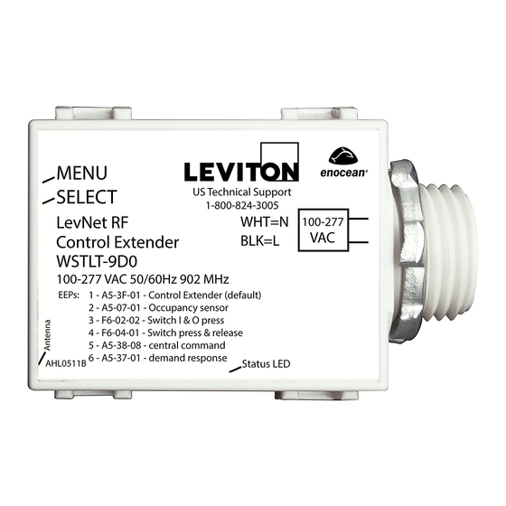
ENOCEAN CONTROL TRANSMITTER
Power Input: 100-277 VAC, 50/60 Hz
Cat. No. WSTLT-9D0
INSTALLATION
EEPS:
1 - A5-3F-01 - Control Extender (default)
EQUIPMENT NEEDED FOR INSTALLATION
• Slotted/Philips Screwdriver
• Wire Nuts/ Connectors
• Electrical Tape
CHOOSE THE OPTIMAL MOUNTING LOCATION
The long term reliability and wireless performance of the Relay is strongly influenced by
the mounting location. Choose a mounting location carefully. For best radio performance:
• Straighten antenna out and away from metal.
• Create separation distance away from interfering electronics such as fluorescent
tube ends, electronic transformers/power supplies, motors, etc.
• Avoid mounting inside metal enclosures.
• Obstructions of metal, concrete and dense building materials will reduce the range.
Mount higher and away from obstructions to maximize the range.
• Confirm operating environment does not exceed temp. or humidity specifications.
• Site survey tools are available to help fine tune wireless communications.
INSTALLATION
1. WARNING: TO AVOID FIRE, SHOCK, OR DEATH; TURN OFF POWER at circuit
breaker or fuse and test that power is off before wiring!
2. PLAN: Identify best mounting locations for receiver and transmitter. Perform
range test to confirm operation prior to installation.
3. CONNECT: Connect the Control Transmitter to circuit following wiring diagram
and local electrical codes. Restore power.
4. LINK: Follow Instructions provided with receiver. Press and release MENU button
to send Link signal.
5. TEST: Use the Sensor Link Test Mode (below) to test operation.
LINKING INSTRUCTIONS
Refer to the Receiver installation guide for Linking instructions. Press and release the
MENU button to send a Link signal during the linking process.
SENSOR LINK TEST MODE
Some receivers support Sensor Link Test Mode. If supported, after Linking, press the
MENU button on the Control Transmitter 5 times to activate the Sensor Link Test Mode
in any linked receivers. Subsequent presses of the MENU button will cause receivers
to toggle:
1) to confirm that the Control Transmitter is linked.
2) to test the reliability of wireless communications.
Receivers will time out of Sensor Link Test Mode after 60 seconds of inactivity.
DIMENSIONS
1.73"
(44 mm)
1.60"
(34.8 mm)
DI-001-WSTLT-00B
English
1.09"
(27.7 mm)
Advertisement
Table of Contents

Related Manuals for Leviton Enocean WSTLT-9D0


Summary of Contents for Leviton Enocean WSTLT-9D0
- Page 1 • If you are unsure about any part of these instructions, consult an electrician. • This product is intended only for use indoors and in dry locations. NOTES: • For use with Leviton ® LevNet RF™ 902 MHz products. • It may be more convenient to link the wireless controls to the Control Transmitter prior to final installation.
- Page 2 LIMITED 5 YEAR WARRANTY AND EXCLUSIONS Leviton warrants to the original consumer purchaser and not for the benefit of anyone else that this product at the time of its sale by Leviton is free of defects in materials and workmanship under normal and proper use for five years from the purchase date.
Need help?
Do you have a question about the Enocean WSTLT-9D0 and is the answer not in the manual?
Questions and answers