Advertisement
Quick Links
WARNINGS AND CAUTIONS:
• TO AVOID FIRE, SHOCK OR DEATH; TURN OFF POWER AT CIRCUIT BREAKER OR FUSE AND TEST THAT POWER IS OFF BEFORE WIRING!
• To be installed and/or used in accordance with electrical codes and regulations.
• If you are unsure about any part of these instructions, consult an electrician.
• Decora
®
Digital remotes are not compatible with standard 3-way or 4-way switches. They must be used with compatible Decora
for multi-location switching.
INTRODUCTION
Decora
®
Digital Remotes are designed to provide multi-location control of
Decora Digital Dimmers and Switches. Decora
®
Digital Dimmers and Switches
with Bluetooth
®
represent the next generation of lighting control technology.
This innovative device works using the Leviton Decora
®
Digital Dimmer &
Timer app that can be easily downloaded to smartphones or tablets and paired
to the Leviton Dimmer using Bluetooth
®
technology. Decora
®
Digital Devices
give users point-to-point local control to automate lighting, bridging the gap
between standard dimmers and whole-house automation systems.
The Decora
®
Digital Dimmer is a powerful device – combining the best
of Leviton dimmer and timer functions with today's mobile technology for
impressive results. The simple touch of a finger following the intuitive on-
screen guide makes it more convenient than ever to manage lighting for home
®
activities or to ensure a "lived-in" look while away. Plus, the Decora
Digital
Dimmer is Universal and compatible with LED, CFL or Incandescent bulbs.
The Decora
®
Digital Switch combines the functions of a standard wall switch
and a countdown or programmable timer switch in one attractive device.
Use of the app allows greater flexibility for accurate timer functionality and
makes pushing buttons for timed events a tedious chore of the past.
The Leviton Decora
®
Digital Dimmer & Timer app can be easily downloaded
to mobile devices and is compatible with Android and iOS smartphones or
tablets. The app is easy to use with simple, intuitive on-screen menu options
to independently control dimmers and switches throughout the home.
Decora
®
Digital Devices are ideal for living rooms, bedrooms, kitchens, dining
rooms, home offices, outdoor lighting or anywhere full control of lighting is
desired.
FEATURES
• Three way communication
• Ease of installation – No new wiring
TOOLS NEEDED TO INSTALL YOUR REMOTE
Slotted/Phillips Screwdriver
Electrical Tape
Pliers
Pencil
Cutters
Ruler
Changing the color of your Remote:
Your remote may include color options. To change color of the face proceed
as follows:
Push in sides at
Insert top tabs
bottom tabs and
and press in
pull outward to
bottom tabs to
release
attach
INSTALLING YOUR REMOTE
NOTE: Use check boxes
when Steps are completed.
WARNING:
Step 1
TO AVOID FIRE, SHOCK OR DEATH; TURN
OFF POWER at circuit breaker or fuse and test that power
is off before wiring!
OFF
ON
OFF
ON
OFF
ON
OFF
ON
OFF
ON
OFF
ON
OFF
ON
OFF
ON
OFF
ON
OFF
ON
OFF
ON
OFF
ON
®
Digital devices
Identifying your wiring application
Step 2
(most common):
NOTE: If the wiring in the wall box does not resemble
any of these configurations, consult an electrician.
1
1
2
2
3
3
4
4
5
5
6
3-Way
4-Way
1. Line or Load (Tagged)
1. First Traveler (note color)
2. Neutral
2. Second Traveler (note color)
3. Ground
3. Neutral
4. First Traveler (note color)
4. Ground
5. Second Traveler (note color)
5. Third Traveler (note color)
NOTE: The first traveler wire is
6. Fourth Traveler (note color)
used to carry line power to the
NOTE: The first and third traveler
other switch box.
wires are used to carry line power
to the other switch boxes.
IMPORTANT:
For 3-Way applications, note that one of the screw terminals from the old
switch being removed will usually be a different color (Black) or labeled
Common. Tag that wire with electrical tape and identify as the common
(Line or Load) in both the dimmer wall box and remote wall box.
For 4-Way applications, note that the old switch being removed will have
4 screws plus a ground screw. Tag the two wires connected to the two back
screw terminals.
Preparing and connecting wires:
Step 3
This remote can be wired using side wire terminal screws or
through backwire openings.
1
Strip Gage
(measure bare
(1.6 cm)
wire here)
Cut
(if necessary)
2
Side Wire Connection
Back Wire Connection
Side wire terminals accept
Back wire openings accept
#14-12 AWG solid copper
#14-12 AWG solid copper
wire only.
wire only.
• Make sure that the ends of the wires from the wall box are
straight (cut if necessary).
• Remove insulation from wires in the wall box as shown.
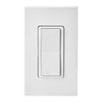
3-Way or More Applications (Multi-location)
Universal Coordinating Switching Remote
Cat. No. DD0SR-01Z - 120VAC, 60Hz
INSTALLATION INSTRUCTIONS
WARNINGS AND CAUTIONS:
• Use this device WITH COPPER OR COPPER CLAD WIRE ONLY.
• Use only one (1) Decora
®
Digital dimmer or switch in a multi-location circuit with up to 9 coordinating remotes.
NOTE: The remote(s) will turn the light on at the brightness level selected at the dimmer.
• Recommended minimum wall box depth for remotes is 2-1/2".
• Maximum wire length from dimmer or switch to all installed remotes cannot exceed 300 ft (90 m).
3-Way Wiring - DDS15 Switch with DD0SR-01Z Coordinating
Step 4a
Remote Application:
DD0SR-01Z
Coordinating Remote
DDS15 Switch
Neutral to Terminal
Screw marked
White (WH)
Terminal
Terminal
Screw
Screw
2
marked
marked
WH
BK
Black (BK)
Black (BK)
1
RD
YL/R D
Terminal
4
Terminal
Screw
3
Screw
marked
marked
5
Yellow/Red
Yellow/Red
Terminal
(YL/RD)
(YL/RD)
Screw marked
Red (RD)
DD0SR-01Z Coordinating Remote
DDS15 Switch
BK
WH
WH
(unused)
Black
RD
YL/RD
RD
(unused)
Load
Green
Green
Ground
Ground
White
NOTE: The DD0SR-01Z coordinating remote must be installed in a wall box with a Neutral connection.
WIRING DD0SR-01Z COORDINATING REMOTE (wall box with load connection):
Connect wires per WIRING DIAGRAM as follows:
NOTE: "BK" and "RD" terminals on coordinating remote are unused. Tighten both screws.
• Green or bare copper wire in wall box to Green terminal screw.
• Load wall box wire identified (tagged) when removing old switch to First Traveler (note color as above).
• Second Traveler wall box wire (note color as above) to terminal screw marked
"YL/RD". This traveler from the remote must go to the terminal screw on the switch marked "YL/RD".
• Neutral wall box wire to terminal screw marked "WH".
WIRING DDS15 SWITCH (wall box with line hot connection):
Connect wires per WIRING DIAGRAM as follows:
• Green or bare copper wire in wall box to Green terminal screw.
• Line Hot (common) wall box wire identified (tagged) when removing old switch to terminal screw marked "BK".
5/8"
• First Traveler wall box wire to terminal screw marked "RD" (note wire color).
• Remove Red insulating label from terminal screw marked "YL/RD".
• Second Traveler wall box wire to terminal screw marked "YL/RD" (note wire color). This traveler from the
switch must go to the terminal screw on the remote marked "YL/RD".
• Neutral wall box wire to terminal screw marked "WH".
• Proceed to Step 5.
3-Way Wiring - DDL06 Dimmer with DD0SR-01Z Coordinating
Step 4b
Remote Application:
DD0SR-01Z
Coordinating Remote
DDL06 Dimmer
Neutral to Terminal
Screw marked
White (WH)
Terminal
Terminal
Screw
Screw
2
marked
marked
WH
BK
Black (BK)
Black
(BK)
1
RD
YL/R D
Terminal
4
Terminal
Screw
3
Screw
marked
marked
5
Yellow/Red
Yellow/
Terminal
(YL/RD)
Red
Screw marked
(YL/RD)
Red (RD)
3-Way Wiring - DDL06 Dimmer with DD0SR-01Z Coordinating Remote
Step 4b
Application:
DD0SR-01Z Coordinating Remote
Terminal
Screw marked
White (WH)
WH
Black
(unused)
2
WH
BK
Load
1
Green
Ground
RD
YL/R D
4
3
White
5
Terminal
Screw marked
Red (RD)
NOTE: The DDL06 dimmer must be installed in a wall box that has a Load connection. The DD0SR-01Z
coordinating remote must be installed in a wall box with a Neutral connection.
WIRING DD0SR-01Z COORDINATING REMOTE (wall box with load connection):
Connect wires per WIRING DIAGRAM as follows:
NOTE: "BK" and "RD" terminals on coordinating remote are unused. Tighten both screws.
Hot (Black)
• Green or bare copper wire in wall box to Green terminal screw.
BK
• Load wall box wire identified (tagged) when removing old switch to First Traveler (note color as above).
• Second Traveler wall box wire (note color as above) to terminal screw marked "YL/RD". This traveler from
the remote must go to the terminal screw on the dimmer marked "YL/RD".
YL/RD
Line
• Line Neutral wall box wire to terminal screw marked "WH".
120 VAC
WIRING DDL06 DIMMER (wall box with line hot connection):
60Hz
Connect wires per WIRING DIAGRAM as follows:
• Green or bare copper wire in wall box to Green terminal screw.
• Line Hot (common) wall box wire identified (tagged) when removing old switch to terminal screw marked "BK".
• First Traveler wall box wire to terminal screw marked "RD" (note wire color).
• Remove Red insulating label from terminal screw marked "YL/RD".
Neutral (White)
• Second Traveler wall box wire to terminal screw marked "YL/RD" (note wire color). This traveler from the
dimmer must go to the terminal screw on the remote marked "YL/RD".
• Proceed to Step 5.
3-Way Wiring - DDL06 Dimmer with DD0SR-01Z Coordinating Remote
Step 4c
(no neutral) Application:
DD0SR-01Z
Coordinating Remote
Terminal
Screw
marked
WH
BK
Black (BK)
RD
YL/ RD
Terminal
Screw
marked
Yellow/Red
(YL/RD)
Coordinating Remote
Black
WH
(unused)
2
BK
Load
RD
1
RD
YL/R D
4
3
Green
Ground
5
White
Terminal
Screw marked
Red (RD)
DI-000-DD0SR-02A
DDL06 Dimmer
Hot (Black)
BK
BK
(unused)
RD
YL/RD
RD
YL/RD
Line
120 VAC
60Hz
Green
Ground
Neutral (White)
DDL06 Dimmer
Terminal
Screw
2
2
marked
BK
Black
(BK)
1
1
RD
YL/ RD
4
4
Terminal
3
Screw
3
marked
5
5
Yellow/
Terminal
Terminal
Red
Screw marked
Screw marked
(YL/RD)
Red (RD)
Red (RD)
DD0SR-01Z
DDL06 Dimmer
Hot (Black)
BK
BK
RD
YL/RD
YL/RD
Line
120 VAC
60Hz
Green
Ground
Neutral (White)
Advertisement

Subscribe to Our Youtube Channel
Related Manuals for Leviton decora DD0SR-01Z


Summary of Contents for Leviton decora DD0SR-01Z
- Page 1 The Decora ® Digital Dimmer is a powerful device – combining the best Load 60Hz Green Green of Leviton dimmer and timer functions with today’s mobile technology for Ground Ground YL/R D YL/R D Terminal Terminal impressive results. The simple touch of a finger following the intuitive on-...
- Page 2 1-800-824-3005. This warranty excludes and there is disclaimed liability for labor for removal of this product or reinstallation.
- Page 3 COMMENTS : The information in this document is the exclusive PROPRIETARY property of LEVITON MANUFACTURING COMPANY, INC. It is disclosed with the understanding that acceptance or review by the recipient constitues an undertaking by the recipient. (1) to hold this information in strict confidence, and (2) not to disclose, duplicate, copy, modify or use the information for any purpose other than that for which disclosed.
Need help?
Do you have a question about the decora DD0SR-01Z and is the answer not in the manual?
Questions and answers