Table of Contents
Advertisement
Available languages
Available languages
US
-INSTRUCTION MANUAL FOR WIRE WELDING MACHINE
F
-MANUEL D'INSTRUCTIONS POUR POSTE A SOUDER A FIL
E
-MANUAL DE INSTRUCCIONES PARA SOLDADORA DE HILO
Spare parts and electrical schematic
Pièces détachées et schéma électrique
Partes de repuesto y esquema eléctrico
3.300.068
sel.: 22 ÷ 24
Pagg. Sid.
page 2
page 8
pag. 15
29/08/14
Advertisement
Table of Contents

Related Manuals for CHIEF MultiMig 511


Summary of Contents for CHIEF MultiMig 511
- Page 1 -INSTRUCTION MANUAL FOR WIRE WELDING MACHINE page 2 -MANUEL D’INSTRUCTIONS POUR POSTE A SOUDER A FIL page 8 -MANUAL DE INSTRUCCIONES PARA SOLDADORA DE HILO pag. 15 Spare parts and electrical schematic sel.: 22 ÷ 24 Pièces détachées et schéma électrique Pagg.
-
Page 2: Safety Precautions
INSTRUCTION MANUAL FOR WIRE WELDING MACHINE IMPORTANT: BEFORE STARTING THE EQUIPMENT, reached the end of its life must be collected separately READ THE CONTENTS OF THIS MANUAL, WHICH and returned to an environmentally compatible recycling MUST BE STORED IN A PLACE FAMILIAR TO ALL US- facility. -
Page 3: Protection Devices
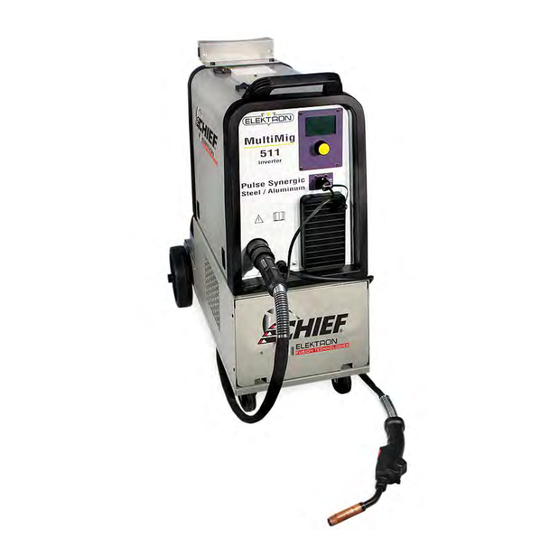
3 CONTROLS LOCATED ON FRONT PANEL. Do not remove or paint over (cover) label. 2 GENERAL DESCRIPTIONS The MULTIMIG 511 welding machine is a system suitable for synergic MIG/MAG and pulsed synergic MIG/MAG welding, developed with inverter technology. It is equipped with a 2-roller gearmotor. - Page 4 B - KNOB Selects and adjusts both the welding functions and parameters. C – CENTRALIZED COUPLING To which the welding torch must be connected. D – EARTH LEAD H – CONNECTOR This is where the control cable of the Push Pull welding torch (P/N EL900007) is connected.
- Page 5 displayed. To display the set values, the handle B will have to be moved slightly, while, by pushing the torch button without welding, the display screen A shows the empty voltage value and a current value of 0. NOTE If 0.6mm diameter wires are used the welding torch sheath should be replaced with one of suitable internal diameter.
- Page 6 of the 2 modes by means of the knob B and press the knob B for less than 2 seconds to confirm the choice. This operation always returns us to the previous display page (PROCESS PARAMS). • PP Force. Adjustment can vary from -99 to +99. By using Push-Pull torch function PPF (Push Pull For- ce) is enabled which adjusts the drive torque of the push-pull motor in order to make the wire feed linear.
-
Page 7: Generator Maintenance
highlighting the word ALL and briefly pressing the knob B reset is made and the display screen A shows Factory Done!! This indicates the reset has been successful. To return to the previous display page, simply press the knob B for more than 2 seconds. • Pre Gas NOTE. - Page 8 MANUEL D’INSTRUCTIONS POUR POSTE A SOUDER A FIL IMPORTANT: AVANT LA MISE EN MARCHE DE LA MA- vapeurs explosifs. Manier avec soin les bouteilles et les CHINE, LIRE CE MANUEL ET LE GARDER, PENDANT détendeurs de pression utilisés dans les opérations de TOUTE LA VIE OPÉRATIONNELLE, DANS UN ENDROIT soudure.
-
Page 9: Explication Des Données Techniques
2 DESCRIPTIONS GENERALES 3 COMMANDES SUR LE PANNEAU AVANT Le poste à souder MULTIMIG 511 est un poste approprié A - ÉCRAN. pour le soudage MIG/MAG synergique et MIG/MAG Il affiche aussi bien les paramètres de soudage que pulsé... - Page 10 5 MISE EN PLACE ET ASSEMBLAGE POUR SOUDURE MIG AVEC GAZ L’installation de cette machine doit être faite par du personnel expert. Ne placez pas le poste à souder sur le sol avec une incli- naison de plus de 10°. Assurez-vous que la tension d'alimentation est 230V 50/60Hz et 30 ampères minimum.
- Page 11 Vérifier que le câble de masse D, à l'intérieur du Relier l'embout du câble de masse, placé à l'intérieur compartiment bobine, est connecté au pôle négatif du compartiment bobine, au pôle positif (voir (voir plaquette des instructions située à côté des plaquette des instructions située à côté des bornes bornes + et -). + et -). •...
- Page 12 Les fonctions pouvant être sélectionnées sont: temps de pause entre deux points ou deux traits de • Courbe synergique (Wire Selection). soudage ; le temps de pause peut varier de 0 (OFF) à Pour choisir la courbe synergique, il faut sélectionner 5 secondes. Pour accéder aux fonctions Spot Time et Pause et appuyer sur la courbe proposée sur l'écran Time, il faut appuyer pendant au moins 2 secondes...
- Page 13 • Post Gas • Burnback AUTO Le réglage peut varier de - 9,9 à +9,9. Il sert à régler la Le réglage peut varier de 0 à 25 sec. longueur du fil sortant de la buse gaz après la soudure. Pour accéder à la fonction, il suffit de la sélectionner À...
-
Page 14: Entretien Du Generateur
8 ENTRETIEN Toute opération d'entretien doit être EFFECTUÉE PAR DU PERSONNEL QUALIFIÉ CONFORMÉMENT À LA NORME IEC 60974-4. 8.1 ENTRETIEN DU GENERATEUR En cas d'entretien à l'intérieur de l'appareil, il faut s'assurer que l'interrupteur F est bien sur la position "0" et que le cordon d'alimentation est débranché... - Page 15 MANUAL DE INSTRUCCIONES PARA SOLDADORA DE HILO IMPORTANTE: ANTES DE LA PUESTA EN FUNCIONA- caciones contenidas en la norma armonizada IEC 60974- MIENTO DEL APARATO, LEER EL CONTENIDO DE ESTE 10 (Cl. A) y se deberá usar solo de forma profesional en MANUAL Y CONSERVARLO, DURANTE TODA LA VIDA un ambiente industrial.
-
Page 16: Descripciones Generales
3 MANDOS SITUADOS EN EL TABLERO ANTERIOR. 2 DESCRIPCIONES GENERALES A - DISPLAY. El aparato MULTIMIG 511 es un sistema idóneo para la Visualiza tanto los parámetros de soldadura como todas soldadura MIG/MAG sinérgico y MIG/MAG pulsado si- las funciones de soldadura. - Page 17 F - INTERRUPTOR. Enciende y apaga la máquina G - CABLE DE RED. 5 COLOCACIÓN E INSTALACIÓN PARA SOLDADURA MIG CON GAS La instalación de la soldadora deberá ser realizada por personal experto. No instalar la soldadora sobre piso con inclinación supe- rior a 10°.
- Page 18 en acero del adaptador, hasta que salga del adaptador desarrollo del software, además del número de release de mismo. las curvas sinérgicas. • Montar el soplete de soldadura. Inmediatamente después del encendido el display A Después de montar la bobina y el soplete, encender la visualiza: máquina, elegir la curva sinérgica adecuada, siguiendo La curva sinérgica utilizada, el modo de soldadura 2T o...
- Page 19 • Process Para elegir o confirmar el tipo de soldadura, es nece- sario, mediante la empuñadura B, seleccionar y pre- sionar, por al menos 2 segundos Short o Pulsed. Short indica que el tipo de soldadura elegido es short sinérgico. Pulsed indica que el tipo de soldadura elegido es pul- sado sinérgico.
- Page 20 • Burnback AUTO El ajuste puede variar desde el 0 a 25 sec. El ajuste puede variar desde -9,9 a +9,9. Sirve para Para acceder a la función es suficiente evidenciarla regular la longitud del hilo que sale de la tobera gas usando la manecilla B y presionándola por menos después de la soldadura.
-
Page 21: Mantenimiento Generador
8 MANTENIMIENTO Cada intervención de mantenimiento debe ser efectuada por personal cualificado según la norma IEC 60974-4. 8.1 MANTENIMIENTO GENERADOR En caso de mantenimiento en el interior del aparato, asegurarse de que el interruptor F esté en posición “O” y que el cable de alimentación no esté... - Page 22 When ordering spare parts please always state the ma- chine item and serial number and its purchase data, the spare part position and the quantity.
- Page 23 DESCRIPTION DESCRIPTION SWIVELING WHEEL HINGED SIDE PANEL HINGE REST FIXED SIDE PANEL GAS CYLINDER SUPPORT COIL SUPPORT BELT INSIDE BAFFLE POWER SOURCE SUPPORT REINFORCEMENT BOTTOM SOLENOID VALVE AXLE BACK PANEL SWITCH FIXED WHEEL FRAME FIXED SIDE PANEL INPUT CABLE TORCH SUPPORT FAN SUPPORT COVER MOTOR WITH FAN...
Need help?
Do you have a question about the MultiMig 511 and is the answer not in the manual?
Questions and answers