Advertisement
Quick Links
Distributed in North America by Ace Hobby Distributors, Inc. • 116 W 19th ST, Higginsville, MO 64037
This kit is guaranteed to be free from defects in material and workmanship at the date of purchase.
It does not cover any damage caused by use or modification. The warranty does not extend beyond the
product itself and is limited only to the original cost of the kit. By the act of building this user-assembled
kit, the user accepts all resulting liability for damage caused by the final product. If the buyer is not
prepared to accept this liability, it can be returned new and unused to the place of purchase for a refund.
This is not a toy. Assembly and flying of this product requires adult supervision.
Read through this book completely and become familiar with the assembly and flight of this airplane.
Inspect all parts for completeness and damage. If you encounter any problems, call 660-584-6724 for help.
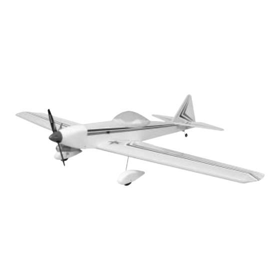
Cloud Dancer 40 ARF
Assembly Manual
Thunder Tiger Cloud Dancer 40 ARF (TTR4542)
660-584-7121 • www.acehobby.com • service@acehobby.com
Notice: Adult Supervision Required
Warranty
1
Specifications:
Wingspan:
60"
Length:
46.75"
Wing area:
625 in
2
Weight:
4lbs
Engine:
.40-.46 2 Cycle
.40-.53 4 Cycle
Radio:
4 Channel
21041/JE6439
Advertisement

Subscribe to Our Youtube Channel
Related Manuals for THUNDER TIGER Cloud Dancer 40 ARF TTR4542


Summary of Contents for THUNDER TIGER Cloud Dancer 40 ARF TTR4542
- Page 1 .40-.46 2 Cycle .40-.53 4 Cycle Radio: 4 Channel Thunder Tiger Cloud Dancer 40 ARF (TTR4542) Distributed in North America by Ace Hobby Distributors, Inc. • 116 W 19th ST, Higginsville, MO 64037 660-584-7121 • www.acehobby.com • service@acehobby.com Warranty This kit is guaranteed to be free from defects in material and workmanship at the date of purchase.
-
Page 2: Optional Retracts
INTRODUCTION All of us at Thunder Tiger want to thank you for choosing one of the finest 40 sized sport planes available, the Cloud Dancer 40. Designed by the late Fred Reese, this airplane offers a unique appearance and sprightly, yet predictable performance. This model features state-of-the-art engineering that provides quick and easy assembly of a strong, yet lightweight airplane that will give you an enjoyable and thrilling experience. -
Page 3: Degree
Extra Glow Plug(s) CARR Engine - The Thunder Tiger PRO-46 is the ideal engine for this air- plane. It is a quiet running engine that is easy to start and require no special break- in period, is very easy to maintain, and will last for years. -
Page 4: Table Of Contents
PARTS DRAWINGS IMPORTANT Please check the contents of your kit box with these part sketches before beginning construction. This will not only familiarize you with the parts and their names, but it will also give you a head start in the unlikely event that you are missing a part. AS6128 Fuselage Fuselage(1) AS6129 Wing Set... -
Page 5: Trim Tape
PARTS DRAWINGS Replacement parts must be ordered by Set Number 3296 Wheel AS6130 Tail Feathers 57mm 2 1/4" Wheel(2) H. Stab/Elevator(1) CA Hinge(7) V. Fin/Rudder(1) 3102 Adjustable Engine Mount AS6131 Cockpit/Canopy Cockpit(1) Beam(2, left/right) Engine Mount Plate(1) Canopy(1) 6/32 x18mm 3mm x 15mm screw(4) Self-Tapping Screw(4) -
Page 6: Wing
WING ASSEMBLY I. Pre-Assembly Notes Please assemble your model according to these instructions. Do not attempt to modify or change in any way as doing so may adversely change its flying characteristics. Before you begin, please check the entire contents of this kit against the parts list and photo to make sure that no parts are missing or damaged. -
Page 7: Wing Assembly
WING ASSEMBLY Join the two wing halves and firmly press wing panels together. Wipe off any excess epoxy with a paper towel and rubbing alcohol. Make sure the two panels are accurately aligned with each other and hold together with several strips of masking tape. Place the servo tray on the top surface of the wing. -
Page 8: Retract Installation
RETRACT INSTALLATION IV. Retract Installation (Optional) See page 2 for a discussion on the retracts we recommend. Begin by hinging the ailerons to the wing panels as shown in the section on fixed gear. Epoxy the wing halves together, making sure you coat all sides of the dihedral brace plus where the ribs join. -
Page 9: Pushrod
RETRACT INSTALLATION Mount the retract servo and bend the pushrods as shown for proper clearance. Glue the wheel wells into the wing using a compatible glue such as “Zap-a-dap-a-goo”, RC 56, or “Shoe-Goo”. Connect the pushrods to the retract servo arm with “Z” bends or “EZ”... - Page 10 FUSELAGE V. Wing Bolts 5/8” 1” The wing is attached to the fuselage using two bolts and blind nuts. Locate three metal clevises, two for elevator pushrod and one for Begin by installing the blind nuts in the wing mounting plate which is rudder.
- Page 11 FUSELAGE/RUDDER VII. Rudder and Tailwheel Locate the two elevator halves and four of the C.A. hinges. Also Locate the rudder and three CA hinges and the control horn and locate two control horns for the elevators. You will also need four two 2mm x 16mm screws.
-
Page 12: Rubber
CANOPY/FUELTANK/MOTOR MOUNT Assemble the fuel tank by first cutting the silicone tube to 2- ⁄ " in length. Press the straight plastic nipple (the 90˚ nipple is not used in this plane) into the rubber stopper (saliva will ease insertion.) Now slip the silicone tubing onto the nipple and insert the metal clunk into the other end of the tubing. - Page 13 RADIO/CG/FLIGHT XI. Cowl Rudder = 2” Right and Left Elevator = 3/4” Up and Down Ailerons = 3/8” Up and Down (Throws are measured at the rearmost edge of the surface.) XIV. Locate A Good Flying Site Generally, the best place to fly your model is at an AMA (Academy of Model Aeronautics) chartered club field.
- Page 14 Range check the radio both with and without the engine running! Follow the radio manufacturers instructions for this. TTR9800 Thunder Tiger F-54S The F-54S is the perfect engine for your XVIII. Post-flight Checks Cloud Dancer, with plenty of power and Be sure that both the transmitter and receiver switches are turned off.
- Page 15 TTR4550 G-202 140 Wing Span: 70 in Wing Area: 1022 in Length: 70 in Weight: 10-10.5 lbs Engine: 1.08-1.6 2 Cycle 1.2-1.8 4 Cycle Radio: 4 Channel w/5 Servos G-202 U L T R A C O T E C O V E R E D hunder Tiger’s first venture This Almost-Ready-To-Fly air- into giant scale aerobats is...
- Page 16 Now you can harken back to This Almost-Ready-To-Fly air- TTR4557 Tiger Bipe a time when pilots were pilots plane is meticulously built from Wing Span: Top 49 in and real airplanes had two balsa/ply covered with Bottom 46 in Wing Area: 635 in wings.
Need help?
Do you have a question about the Cloud Dancer 40 ARF TTR4542 and is the answer not in the manual?
Questions and answers