Table of Contents
Advertisement
Quick Links
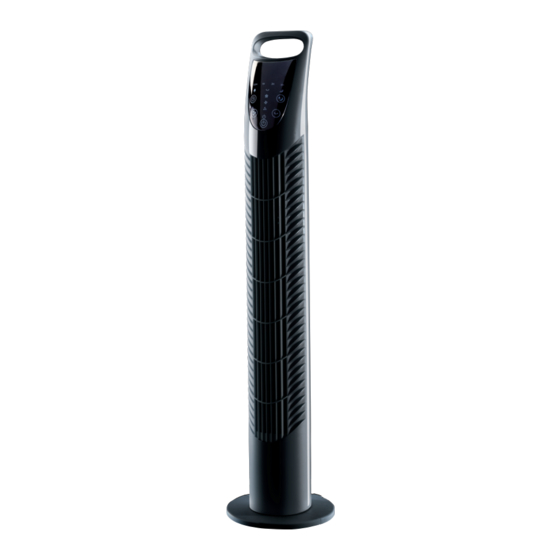
31" TOWER
FAN
09125
These instructions accompanying the product are the original instructions. This document is part of the product,
keep it for the life of the product passing it on to any subsequent holder of the product. Read all these
instructions before assembling, operating or maintaining this product.
This manual has been compiled by Draper Tools describing the purpose for which the product has been
designed, and contains all the necessary information to ensure its correct and safe use. By following all the
general safety instructions contained in this manual, it will ensure both product and operator safety, together
with longer life of the product itself.
AlI photographs and drawings in this manual are supplied by Draper Tools to help illustrate the operation of the
product.
Whilst every effort has been made to ensure the accuracy of information contained in this manual, the Draper
Tools policy of continuous improvement determines the right to make modifications without prior warning.
Advertisement
Table of Contents

Related Manuals for Draper 09125


Summary of Contents for Draper 09125
- Page 1 AlI photographs and drawings in this manual are supplied by Draper Tools to help illustrate the operation of the product.
-
Page 2: Introduction
Commercial copying, redistribution, hiring or lending is prohibited. No part of this publication may be stored in a retrieval system or transmitted in any other form or means without written permission from Draper Tools Limited. In all cases this copyright notice must remain intact. -
Page 3: Table Of Contents
CONTENTS 1. TITLE PAGE 1.1 INTRODUCTION......................2 1.2 REVISION HISTORY ....................2 1.3 UNDERSTANDING THIS MANUAL ................2 1.4 COPYRIGHT NOTICE ....................2 2. CONTENTS 2.1 CONTENTS ........................3 3. GUARANTEE 3.1 GUARANTEE ....................... 4 INTRODUCTION 4.1 SCOPE......................... 5 4.2 SPECIFICATION ......................5 4.3 HANDLING &... -
Page 4: Guarantee
This guarantee applies in lieu of any other guarantee expressed or implied and variations of its terms are not authorised. Your Draper guarantee is not effective unless you can produce upon request a dated receipt or invoice to verify your proof of purchase within the guarantee period. -
Page 5: Introduction
4.1 SCOPE The remote control oscillating tower fan described in this booklet is intended for air flow circulation uses in home or office environments. 4.2 SPECIFICATION Stock No........................... 09125 Part No........................... FAN17 Motor: Rated voltage ........................230V Rated frequency........................50Hz Rated input ..........................40W... -
Page 6: Health And Safety Information
HEALTH AND SAFETY INFORMATION 5.1 GENERAL SAFETY INSTRUCTIONS FOR POWER TOOL USE When using any type of power tool there are steps that should be taken to make sure that you, as the user, remain safe. Common sense and a respect for the tool will help reduce the risk of injury. Read the instruction manual fully. -
Page 7: Additional Safety Instructions For Fans
Warning: Please read the following instructions carefully, failure to do so could lead to serious personal injury. Draper Tools Ltd., recommends that this fan not be modified or used for any application other than that for which is was designed. If you are unsure of its relative applications, do not hesitate to contact us in writing and we will advise you. -
Page 8: Technical Description
TECHNICAL DESCRIPTION 6.1 IDENTIFICATION Infrared remote control unit. Louvred air vents. Display. Transport handle. Control panel. Air inlet. Base. - 8 -... -
Page 9: Unpacking And Checking
Lay the contents out and check them against the parts shown below. If any part is damaged or missing; please contact the Draper Helpline (the telephone number appears on the Title page) and do not attempt to use the machine. -
Page 10: Assembling The Fan
ASSEMBLING THE FAN 8.1 ASSEMBLING THE BASE TO THE FAN BODY Remove the three base securing screws. Bring the 2 halves of the base sections together whilst ensuring the power cable passes though the hole created when assembled. Secure the assembled base to the fan body using the three screws provided. -
Page 11: Fan Instruction
Insert 2 × 1.5AAA† type batteries taking note of the correct polarity, as indicated in the back of the compartment. Securely replace the back cover. †Draper stock No.61833 (not supplied). Note: Do not use rechargeable batteries. - 11 -... -
Page 12: Maintenance
10. MAINTENANCE 10.1 MAINTENANCE The fan requires little maintenance other than occasional cleaning. Before cleaning, remove the plug from the socket. • To ensure adequate air circulation to the motor, keep the rear vents free from dust, etc. by periodically vacuuming them. •... -
Page 13: Explanation Of Symbols
11. EXPLANATION OF SYMBOLS 11.1 EXPLANATION OF SYMBOLS Do not dispose of WEEE* unsorted municipal waste. Class II construction (Double insulated). - 13 -... -
Page 14: Disposal
12. DISPOSAL 12.1 DISPOSAL – At the end of the machine’s working life, or when it can no longer be repaired, ensure that it is disposed of according to national regulations. – Contact your local authority for details of collection schemes in your area. In all circumstances: •... - Page 15 NOTES - 15 -...
- Page 16 ©Published by Draper Tools Limited. No part of this publication may be reproduced, stored in a retrieval system or transmitted in any form or by any means, electronic, mechanical photocopying, recording or otherwise without prior permission in writing from Draper Tools Ltd.
Need help?
Do you have a question about the 09125 and is the answer not in the manual?
Questions and answers