Table of Contents
Advertisement
INSTALLATION GUIDE AND SPECIFICATIONS
GPIB Hardware
Contents
Electromagnetic Compatibility Guidelines .............................................................................. 1
GPIB-USB Interfaces ............................................................................................................... 2
LED Signaling .................................................................................................................. 4
PCIe-GPIB, PCIe-GPIB+, PCI-GPIB, PCI-GPIB+, PCI-GPIB/LP, and PCI-8232................. 5
ExpressCard-GPIB ................................................................................................................... 7
PMC-GPIB ............................................................................................................................... 8
PXI-GPIB and PXI-8232.......................................................................................................... 10
GPIB-ENET/1000 .................................................................................................................... 12
GPIB-ENET/1000 Installation ......................................................................................... 12
Baseplate Identification Label .......................................................................................... 13
Startup............................................................................................................................... 13
Ethernet Connector LEDs................................................................................................. 14
Software Recognition ....................................................................................................... 14
Ethernet Configuration ..................................................................................................... 15
Firmware Update .............................................................................................................. 17
READY LED Signaling ................................................................................................... 17
CFG RESET Switch ......................................................................................................... 18
Specifications............................................................................................................................ 19
ExpressCard-GPIB ........................................................................................................... 19
GPIB-ENET/1000 ............................................................................................................ 20
GPIB-USB-HS.................................................................................................................. 21
GPIB-USB-HS+ ............................................................................................................... 22
PCI-8232........................................................................................................................... 23
PCIe-GPIB and PCIe-GPIB+ ........................................................................................... 25
PCI-GPIB.......................................................................................................................... 26
PCI-GPIB+ ....................................................................................................................... 27
PMC-GPIB ....................................................................................................................... 28
PXI-8232 .......................................................................................................................... 29
PXI-GPIB ......................................................................................................................... 30
All Devices ....................................................................................................................... 32
Worldwide Support and Services ............................................................................................. 34
Electromagnetic Compatibility Guidelines
This hardware has been tested and found to comply with the applicable regulatory requirements
and limits for electromagnetic compatibility (EMC) as indicated in the hardware's Declaration
of Conformity (DoC)
1
. These requirements and limits are designed to provide reasonable
Advertisement
Table of Contents

Subscribe to Our Youtube Channel
Related Manuals for NI ExpressCard-GPIB


Summary of Contents for NI ExpressCard-GPIB
-
Page 1: Table Of Contents
Contents Electromagnetic Compatibility Guidelines ................1 GPIB-USB Interfaces ....................... 2 LED Signaling ........................4 PCIe-GPIB, PCIe-GPIB+, PCI-GPIB, PCI-GPIB+, PCI-GPIB/LP, and PCI-8232....5 ExpressCard-GPIB ........................7 PMC-GPIB ..........................8 PXI-GPIB and PXI-8232......................10 GPIB-ENET/1000 ........................12 GPIB-ENET/1000 Installation ..................12 Baseplate Identification Label ..................13 Startup.......................... -
Page 2: Gpib-Usb Interfaces
To obtain the DoC for this product, visit , search by ni.com/certification model number or product line, and click the appropriate link in the Certification column. 2 | ni.com | GPIB Hardware Installation Guide and Specifications... - Page 3 To prevent damage to your GPIB-USB hardware and other system components, do any of the following: • Ensure that your system and all instruments connected to it share the same ground potential. This eliminates the possibility of voltage differential running through your system.
-
Page 4: Led Signaling
Indicates that the GPIB-USB-HS+ is plugged into a USB Hi-Speed (USB 2.0) port. Blinking Amber Indicates activity on the GPIB bus or that the GPIB Analyzer is or Green capturing. 4 | ni.com | GPIB Hardware Installation Guide and Specifications... -
Page 5: Pcie-Gpib, Pcie-Gpib+, Pci-Gpib, Pci-Gpib+, Pci-Gpib/Lp, And Pci-8232
PCIe-GPIB, PCIe-GPIB+, PCI-GPIB, PCI-GPIB+, PCI-GPIB/LP, and PCI-8232 Electrostatic discharge can damage several components on your GPIB Caution board. To avoid such damage in handling your board, touch the antistatic plastic package to a metal part of your computer chassis before removing the board from the package. - Page 6 Screw the mounting bracket of the GPIB board to the back panel rail of the computer. Replace the top cover (or the access panel to the expansion slot). Power on your computer. The GPIB hardware installation is now complete. 6 | ni.com | GPIB Hardware Installation Guide and Specifications...
-
Page 7: Expresscard-Gpib
™ slot on your computer. Before connecting the ExpressCard-GPIB interface to GPIB devices, ensure that the computer and the GPIB devices are at the same ground potential. If your computer is already running, the operating system automatically detects the GPIB interface. -
Page 8: Pmc-Gpib
Figure 3 shows how to insert the ExpressCard-GPIB and connect the cable. Figure 3. Inserting the ExpressCard-GPIB Notebook Computer ExpressCard Slot ExpressCard-GPIB Cable The GPIB hardware installation is now complete. PMC-GPIB Electrostatic discharge can damage several components on your GPIB Caution board. - Page 9 Insert the PMC-GPIB into the slot as shown in Figure 4. It might be a tight fit, but do not force the board into place. Figure 4. Installing the PMC-GPIB Host Face Plate 5 V Keying Hole Mounting Screws 3.3 V Keying Hole PMC-GPIB Board Use the mounting hardware provided to fasten the PMC-GPIB to the host.
-
Page 10: Pxi-Gpib And Pxi-8232
PXI card in such a slot. If you install the board in a non-master slot, you must disable your PXI card’s onboard DMA controller using the board-level call ibdma. Refer to the NI-488.2 Help for a complete description of ibdma. Remove the filler panel for the peripheral slot you have chosen. - Page 11 Insert your PXI card into the selected 5 V slot. Use the injector/ejector handle to fully inject the device into place. Figure 5 shows how to install your PXI card into a PXI or CompactPCI chassis. Figure 5. Installing Your PXI Card Injector/Ejector Handle (In Down Position) PXI Chassis Your PXI Card...
-
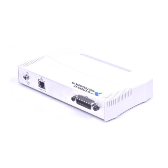
Page 12: Gpib-Enet/1000
You may need to run software configuration and verification utilities at this time. Connect the GPIB cable to the GPIB-ENET/1000. Connect the other end to your GPIB instrument. 12 | ni.com | GPIB Hardware Installation Guide and Specifications... -
Page 13: Baseplate Identification Label
Baseplate Identification Label When you configure the GPIB-ENET/1000 for use on your network, you will need to differentiate it from other network devices. Every GPIB-ENET/1000 has a unique serial number, Ethernet address, and default hostname. You can find this information on the baseplate identification label on the GPIB-ENET/1000. -
Page 14: Ethernet Connector Leds
Off—Indicates you do not have a network link. Software Recognition In Windows, use the GPIB Ethernet Wizard to add the GPIB-ENET/1000 to your system. Launch the GPIB Ethernet Wizard from Start»Programs»National Instruments»NI-488.2. 14 | ni.com | GPIB Hardware Installation Guide and Specifications... -
Page 15: Ethernet Configuration
) Click NI Launcher and select GPIB Ethernet Wizard. Accept the Windows 8 GPIB-ENET/1000 default configuration settings or change them while running the wizard. On Mac and Linux, use the Add GPIB Hardware Wizard to add the GPIB-ENET/1000 to your system. - Page 16 Primary DNS Server/Secondary DNS Server—The IP address of a network device that stores hostnames and translates them into IP addresses. If your network does not have a DNS server, leave these parameters blank. 16 | ni.com | GPIB Hardware Installation Guide and Specifications...
-
Page 17: Firmware Update
GPIB-ENET/1000 in the future. You must update the firmware to take advantage of any new features. You can obtain the latest upgrade by navigating to in a Web browser and entering Info Code ni.com/info GPIBENET1000FW Do not power-off the GPIB-ENET/1000 or disconnect the power supply Caution while updating the firmware. -
Page 18: Cfg Reset Switch
ON/OFF state of the ACT/LINK LED. Have this information available when calling National Instruments. CFG RESET Switch The Configuration Reset (CFG RESET) switch is a recessed switch located beside the power connector on the rear panel. 18 | ni.com | GPIB Hardware Installation Guide and Specifications... -
Page 19: Specifications
Once the READY LED blinks yellow, release the CFG RESET switch. The GPIB-ENET/1000 resets to its default network characteristics and resumes the boot process. The READY LED indicates the boot process progress, as described in Table 3. Specifications ExpressCard-GPIB Performance GPIB 3-wire... -
Page 20: Gpib-Enet/1000
500 mA @ +12 V, Maximum Physical Characteristics Dimensions 21.0 cm × 12.7 cm × 3.7 cm (8.3 in. × 5.0 in. × 1.4 in.) Weight 394 g (13.9 oz) 20 | ni.com | GPIB Hardware Installation Guide and Specifications... -
Page 21: Gpib-Usb-Hs
Connector GPIB IEEE 488 standard 24 pin Ethernet RJ-45 with integrated LEDs Environment Operating ambient temperature 0 °C to 55 °C (Tested in accordance with IEC 60068-2-1 and IEC 60068-2-2.) Operating relative humidity 10% to 90%, noncondensing (Tested in accordance with IEC 60068-2-56.) Storage ambient temperature -40 °C to 70 °C (Tested in accordance with IEC 60068-2-1 and... -
Page 22: Gpib-Usb-Hs
(Tested in accordance with IEC 60068-2-1 and IEC 60068-2-2.) Storage relative humidity 5% to 95%, noncondensing (Tested in accordance with IEC 60068-2-56.) GPIB-USB-HS+ Performance GPIB 3-wire up to 1830 kbytes/s HS488 up to 7920 kbytes/s 22 | ni.com | GPIB Hardware Installation Guide and Specifications... -
Page 23: Pci-8232
Power Requirements USB bus-powered device +5 V (VBUS) 80 mA, Typical 500 mA, Maximum Physical Characteristics Dimensions 8.0 cm × 6.1 cm × 2.0 cm (3.2 in. × 2.4 in. × 0.8 in.) Weight 153 g (5.4 oz), includes USB cable weight Connector GPIB IEEE 488 24-pin connector... -
Page 24: Power Requirements
Storage ambient temperature -20 °C to 70 °C (Tested in accordance with IEC 60068-2-1 and IEC 60068-2-2.) Storage relative humidity 5% to 95%, noncondensing (Tested in accordance with IEC 60068-2-56.) 24 | ni.com | GPIB Hardware Installation Guide and Specifications... -
Page 25: Pcie-Gpib And Pcie-Gpib
A version of the PCIe-GPIB controller (part number 190243x-01, manufactured prior to 2008) differs from these specifications in power consumption, physical dimensions, and ambient temperature range. For specific details, refer to the Notice of Board Change—PCIe-GPIB on ni.com GPIB Hardware Installation Guide and Specifications | © National Instruments | 25... -
Page 26: Pci-Gpib
PCI-GPIB/LP is a low profile PCI-GPIB board designed to fit in low-profile machines. It uses a special cable to convert between the micro-DSub connector of the board and the GPIB connector. 26 | ni.com | GPIB Hardware Installation Guide and Specifications... -
Page 27: Pci-Gpib
Connector GPIB IEEE 488 24-pin connector (The PCI-GPIB/LP uses a special cable to convert between the Micro D-Sub connector of the board and the GPIB connector.) Universal Environment Operating ambient temperature 0 °C to 55 °C (Tested in accordance with IEC 60068-2-1 and IEC 60068-2-2.) Operating relative humidity 10% to 90%, noncondensing... -
Page 28: Pmc-Gpib
129 mA, Maximum 3 mA, Typical 10 mA, Maximum Physical Characteristics Dimensions 7.4 cm × 14.9 cm (2.9 in. × 5.9 in.) Connector GPIB Micro D-Sub 25-pin connector 32-bit, Universal Signaling 28 | ni.com | GPIB Hardware Installation Guide and Specifications... -
Page 29: Pxi-8232
Environment Operating ambient temperature 0 °C to 55 °C (Tested in accordance with IEC 60068-2-1 and IEC 60068-2-2.) Operating relative humidity 10% to 90%, noncondensing (Tested in accordance with IEC 60068-2-56.) Storage ambient temperature -20 °C to 70 °C (Tested in accordance with IEC 60068-2-1 and IEC 60068-2-2.) Storage relative humidity 5% to 95%, noncondensing... -
Page 30: Pxi-Gpib
MIL-PRF-28800F, Class 3.) PXI-GPIB Performance GPIB 3-wire up to 1536 kbytes/s HS488 up to 7885 kbytes/s Power Requirements +5 V 80 mA, Typical 165 mA, Maximum 3 mA, Typical 10 mA, Maximum 30 | ni.com | GPIB Hardware Installation Guide and Specifications... -
Page 31: Shock And Vibration
Physical Characteristics Dimensions 16.0 cm × 10.0 cm (6.3 in. × 3.9 in.), 3U Connector GPIB IEEE 488 24-pin connector 32-bit, Universal Signaling Environment Operating ambient temperature 0 °C to 55 °C (Tested in accordance with IEC 60068-2-1 and IEC 60068-2-2.) Operating relative humidity 10% to 90%, noncondensing (Tested in accordance with IEC 60068-2-56.) -
Page 32: All Devices
• AS/NZS CISPR 11: Group 1, Class A emissions • AS/NZS CISPR 22: Class A emissions • FCC 47 CFR Part 15B: Class A emissions • ICES-001: Class A emissions 32 | ni.com | GPIB Hardware Installation Guide and Specifications... - Page 33 . This page contains the environmental regulations and ni.com/environment directives with which NI complies, as well as other environmental information not included in this document. Waste Electrical and Electronic Equipment (WEEE) At the end of the product life cycle, all NI products must be EU Customers disposed of according to local laws and regulations.
-
Page 34: Worldwide Support And Services
NI product. Refer to the Export Compliance Information at ni.com/legal/export-compliance for the NI global trade compliance policy and how to obtain relevant HTS codes, ECCNs, and other import/export data. NI MAKES NO EXPRESS OR IMPLIED WARRANTIES AS TO THE ACCURACY OF THE INFORMATION CONTAINED HEREIN AND SHALL NOT BE LIABLE FOR ANY ERRORS.
Need help?
Do you have a question about the ExpressCard-GPIB and is the answer not in the manual?
Questions and answers