
Related Manuals for 5Gstore UIS-522


Summary of Contents for 5Gstore UIS-522
- Page 1 Remote Power Management Solution for Crashed Network Devices USER MANUAL Version: 2205 (Updated for firmware MNT.NBU.9905)
-
Page 2: Table Of Contents
Table of Contents Chapter 1: Introduction..................1.1. Introduction..............................3 1.2. Hardware Specification ..........................4 1.3. Network Diagram ............................5 1.4. LED Indicators Explained ........................6 Chapter 2: Hardware Setup ..................Chapter 3: Software & Web Setup................3.1. Introduction..............................9 3.2. How to Locate & Access IP Switch in LAN ..................9 3.2.1 Locate IP Switch in LAN using Utility program................. 9 3.2.2 Locate IP Switch in LAN using fixed IP ..................10 3.3. How to Access IP Switch from WAN – using DDNS ..............11 3.4. How to Access IP Switch from WAN - using Hangouts ............11 3.4.1. How to Setup Hangouts........................12 3.4.2. How to Control IP Switch using Hangouts ................13 3.5. How to Access IP Switch from WAN – Using Skype..............14 3.6. How to Access IP Switch from Cloud4UIS.com & Mobile App ..........16 3.7. How to Upgrade/ Re-Flash Firmware ...................17 Chapter 4: IP Switch Web User Interface .............. 4.1. Information ............................... 19 4.1.1 Current Status............................19 4.2 Configuration ............................. -
Page 3: Chapter 1: Introduction
Chapter 1: Introduction 1.1. Introduction IP Switch is designed to automatically power-cycle either one or both of its outlets when either; a) Internet connectivity is lost, OR b) the network device being monitored is no longer responding in LAN. It can also be used to: a) remotely control outlets via instant messaging tools like Google Hangouts and Skype, via cloud management, or via its web user interface. -
Page 4: Hardware Specification
SNTP, DHCP. Operating Temperature: 0°C ~ 60°C; Operating Humidity: 10% ~ 90% For indoor use only. 1.2. Hardware Specification Model No: UIS-522 Socket type 2x of either; a) Universal socket (Type X) b) USA (Type B, NEMA 5-15R) AUST / China (Type I, AS / NZS3112, CCC) -
Page 5: Network Diagram
UIS On/ Off Button 1 button with Blue LED (press & hold to toggle) Other LED Indicator 1x Green for Internet Indicator 1x Green for Cloud Link Indicator Reset to Factory Default Press & hold Outlets 1 & 2 for 10 seconds, then release Internet Indicator Green LED Web Server CPU... -
Page 6: Led Indicators Explained
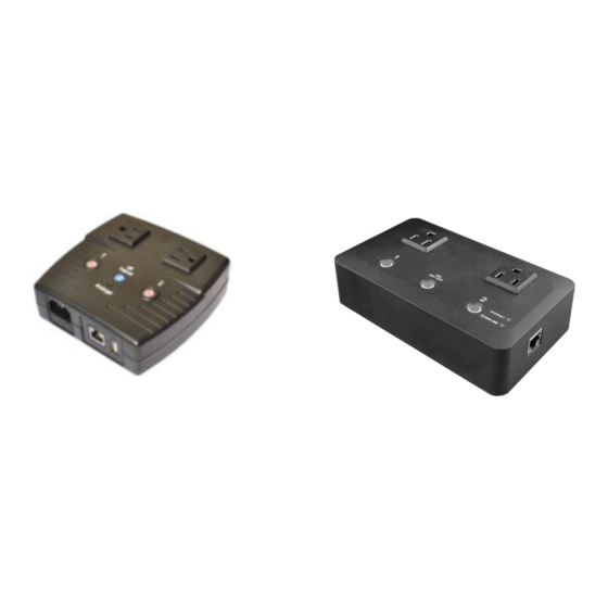
Fig.2 IP Switch setup to keep Internet device alive. 1.4. LED Indicators Explained LED Status for Internet & Outlets LED status Condition description Internet connection available and UIS (Uninterruptable Internet Solid Green Internet System) mode has been activated. There is internet connection, however, at least one of the Blinking Internet target sites is not responsive (regardless of being assigned or... - Page 7 LED Status on LAN Port Light color Condition description When On: Internet speed is at 100M Green When flashing: Data transmitting / receiving On: Internet correspond speed is 10M Yellow Flash: Data transmitting / receiving Fig.3 LED Indicators Fig.4 UIS-522B Hardware Fig.5 UIS-622B Hardware...
-
Page 8: Chapter 2: Hardware Setup
Chapter 2: Hardware Setup IP Switch hardware installation procedure (applies to both models): Step 1: Connect the power cord to device and wall outlet (for UIS-622B power cable is permanently connected). Press the Orange LEDs for 2 seconds to turn the Outlets On or Off. Step 2: Connect the power plug(s) from the device(s) you want to control to IP Switch... -
Page 9: Chapter 3: Software & Web Setup
3.2.1 Locate IP Switch in LAN using Utility program. Step 1: Download Utility program from http://5gstore.com/ipswitchupdates install. Once installed Utility will locate and list IP Switch unit(s). NOTE: Utility can only discover the IP Switch units that are located within the same LAN or network. -
Page 10: Locate Ip Switch In Lan Using Fixed Ip
Step 2: Click “Launch Web User Interface” to open your web browser and access the Web UI of the unit. A password dialog box will appear and prompt you to log in. default; Username/ password admin/ admin. Press “OK” to proceed. Step 3: You will be logged into the IP Switch. -
Page 11: How To Access Ip Switch From Wan - Using Ddns
3.3. How to Access IP Switch from WAN – using DDNS The IP Switch Web User Interface (Web UI) can be accessed remotely from Wide Area Network (WAN). To do so, you must have a public dynamic IP address from your ISP (Internet Service Provider) - if you’re unsure about this, please contact your ISP. -
Page 12: How To Setup Hangouts
3.4.1. How to Setup Hangouts Step 1: From the Utility application, select ‘Launch Web User Interface’ - when prompted, log in with the default user name & password: User Name: admin Password: admin NOTE: If Utility cannot locate your Switch, please refer back... -
Page 13: How To Control Ip Switch Using Hangouts
3.4.2. How to Control IP Switch using Hangouts After setting up and getting connected as above. Bring up the IP Switch chat window by inviting it to chat. *NOTE: Typing in anything other than the Keywords will invoke IP Switch to respond with “Please type HELP to list available commands.”... -
Page 14: How To Access Ip Switch From Wan - Using Skype
3.5. How to Access IP Switch from WAN – Using Skype As an alternative to the Google Talk/ Hangouts, you can now use Skype to monitor and control your outlets. Step 1: Connect your computer to the same network as the IP Switch. Open a web browser to its IP Address (e.g. - Page 15 4. Copy and Paste the ID 5. Toggle back to the Admin Screen 6. Enter the Name for your Switch (any name you want to represent) 7. Paste the ID in the ID field 8. Click Add Step 5: Skype Control 1.
-
Page 16: How To Access Ip Switch From Cloud4Uis.com & Mobile App
Result Other Commands: Outlet 1 or 2: Turn ON/ OFF, Reset UIS: Turn ON/ OFF *NOTE: If you have multiple outlets, you may use the same ID (from Get My ID). 3.6. How to Access IP Switch from Cloud4UIS.com & Mobile The Switch can be controlled at any time, from any where in the world (as long as it has an Internet connection), using the website Cloud4UIS.com as well as via a mobile app called ezDevice (available on the App Store and Google Play Store). -
Page 17: How To Upgrade/ Re-Flash Firmware
Follow these steps for adding the Switch via ezDevice mobile app 1. Connect your mobile device to the same router you have your Switch plugged into so that you are on the same LAN 2. Open the Google Play or App Store and search for: ezDevice 3. - Page 18 connected to the same network as the IP switch or, in certain cases when the IP Switch is unreachable, you may connect it directly to your computer via the Ethernet cable. *NOTE: Before performing the upgrade, it is recommended that you save your settings.
-
Page 19: Chapter 4: Ip Switch Web User Interface
beside 'Location' Step 4: A window will open to view your computer files. The firmware typically saves to your downloads folder. Select the .bin file named and click Open Step 5: You'll now see the file appear next to 'Location’ -> Click Apply to begin the upgrade NOTE: The firmware process takes about 2-5 minutes. -
Page 20: Configuration
Site Label: A name for the target site Target Site: This is the default target site as listed under Configuration page IP Address: The IP address of the Target Site Response Time: based on UDP / TCP protocol sets in Configuration page Timeout: Number of timeouts as a percentage of total tries since reset. - Page 21 Website / IP Address Assign: Assign either one or both outlets to the website / IP address. Outlet assigned to a group of websites will auto reset, when all sites within that group timeout. NOTE: Assignment cannot be for a combination of both and single outlets. Site Label: An easy to remember name for the site.
- Page 22 *NOTE: The target site can be a Domain Name, IP Address or even LAN IP Address – e.g. the router’s IP or local device on the router such as an IP Camera. Your Router IP will be filled in automatically and is meant for cases where user want to ensure that an Auto Reset event is only due to Router crashing, and not just a failure of external IPs.
-
Page 23: Schedule
*NOTE: Power Delays also apply to scheduled or manual resets. Only outlets that are currently powered on will power cycle upon an auto reset. iii. Timeout Settings Timeout for Each Website / IP Address Assigned websites must respond within this time or it is considered a timeout. Set a larger value to allow for occasional Internet lags. -
Page 24: Network
New Schedule Event Item: Select to schedule an event for either Outlet 1 or Outlet 2, both, or UIS Reset. Action: Select action to apply to above Outlets: ON, OFF or RESET. Date (yyyy/mm/dd) Select the event frequency for the above outlet: a. - Page 25 IP Address Hostname By default the hostname (LAN Domain Name) is set to Outlet. This should allow the unit to be located on your router's client list when determining the LAN IP address. *NOTE: If running multiple IP Switch units, assign different hostnames to each. IP Address This determines/ displays the IP Switch’s IP address.
- Page 26 Primary DNS Server IP User can set their preferred DNS server / one that is assigned by ISP. Default is 208.67.222.222. Secondary DNS Server IP Use this to set a Secondary DNS Server IP address. IP Switch will use this if the Primary DNS Server IP address is not working.
-
Page 27: E-Mail
Dynamic DNS (“DDNS”) is a third party service – some providers offer free service, others require a fee. It allows the user to alias a dynamic WAN IP address to a WAN hostname. So no matter how many times your ISP changes the IP address, you will be able to locate your unit over WAN using your DDNS hostname. - Page 28 E-mail Settings E-mail Notification When ‘Enabled’ and settings are applied, user can receive notifications form the Switch. 2 additional sections will appear that also must be configured – ‘Test E-mail’ and ‘E-mail Address Book’ E-mail Server Only SMTP servers are supported (IMAP and HTTP are not). Example: smtp.gmail.com E-mail Port...
-
Page 29: Account
Test E-mail Send a test E-mail Enter a valid e-mail address to send the test email to. Example of email received: iii. E-mail Address Book E-mail Address Book List the users who shall receive an e-mail notification, as they appear in the Event Log section. -
Page 30: Hangouts
Password / Confirm Password Assign a password to the account. The administrator can set up to a 32 case sensitive password. Enter it a 2 time to confirm password. 4.2.6 Hangouts Setup IP Switch to be controllable via Google Hangouts. Hangouts Status This determines the status of the IP Switch’s Gmail account. -
Page 31: System Time
Add Contact Accounts (to access / control the above account) The administrator can assign up to 8 Gmail users who can receive notification, control AND receive IP Switch feedback from their Gmail account. Once assigned, the respective user must then ‘add/invite’ the IP Switch to their Contact list - this chat invitation is generated once the Administrator clicks ‘Send Test Message’. -
Page 32: Language
Edit, delete an existing Time Servers from the list, then, the Add dialog box will appear. Click Back to return to the System Time Settings webpage. Time Zone (Relative to GMT) Select the appropriate time zone. Click Apply to save changes. Daylight Saving Time Using Daylight Saving Time Disabled by default. -
Page 33: Log Information
4.3 Log Information 4.3.1 Event Log This section will log events that occurred on the IP Switch and categorize them. Event Log Type Select which type of log to show: a. All (both Status and Notifications are shown) b. Status Examples of Status logs: UIS On/Off;... -
Page 34: Save / Upgrade
System Information This section shows general hardware information such as the Hardware and Firmware Version, the serial number, Uptime, System Time and when the system last reset. Network Status This section shows all information relating to the Network environment. Hostname This is the default hostname. - Page 35 Restore Use this function to restore a *.cfg configuration. Click Browse/ Choose File and locate the file you saved. Click Restore to apply. Reset to factory default This function will reset all settings to its default configuration. Upgrade Firmware Firmware Version Displays the current firmware version running on the Switch.
-
Page 36: Chapter 5: Troubleshooting Tips
Chapter 5: Troubleshooting Tips 5.1 Common Issues 1. Assign a static IP (manual) address to the Power Switch rather than using DHCP. a. This is a more stable/reliable way of connecting the Switch to your network b. To configure this, you may do so from the WebUI (see section 4.2.3) OR via the Utility program: i. - Page 37 5. Check the Fuse: If your IP Switch is not powering ON, it’s possible the fuse may be bad. Follow the steps below to change out the fuse: For model UIS-522B: a. Remove the Power Cord and Ethernet Cable from your IP Switch before proceeding.
- Page 38 To remove, take something like a flat tipped screwdriver then push the fuse holder in slightly while simultaneously twisting to the left (in the direction of the arrow on the holder). The holder will pop out. Simply slide it straight outward. g.
-
Page 39: Hangouts
You may download current firmware here: http://5gstore.com/ipswitchupdates If you are NOT receiving the Test Message (aka Chat Invite) from the IP Switch account, please do the following (NOTE: If your Gmail does not show the information below follow the steps after the screenshot below step 8 here): 1. - Page 40 3. You should see your name appear with a green dot next to it, which indicates you are signed into Hangouts. If you do NOT see this, there should be a button to “Sign in to Hangouts” – clicking this will sign you in 4.
-
Page 41: Using Accounts With 2-Step Verification
2. In the list of apps that appears, scroll down and click More 3. Select the icon for Hangouts (or it may be listed as Chat) 4. A new window will open to the Hangouts app. You should see a menu on the left. - Page 42 3. Click on the email account at the top right and a window will pop out 4. Click “Manage your Google Account” button 5. A new window will open showing Google Account 6. Select “Security” on the left 7. Scroll down to the “Signing in to Google” section 8.
Need help?
Do you have a question about the UIS-522 and is the answer not in the manual?
Questions and answers