Samsung Duct Type Series Installation Manual
Hide thumbs
Also See for Duct Type Series:
- User manual (12 pages) ,
- User manual (19 pages) ,
- User & installation manual (43 pages)
Advertisement
Table of Contents
- 1 Table of Contents
- 2 Safety Precautions
- 3 Accessories
- 4 Selecting the Installation Location
- 5 Indoor Unit Installation
- 6 Purging the Unit
- 7 Connecting the Refrigerant Pipe
- 8 Cutting/Flaring the Pipes
- 9 Performing Leak Test & Insulation
- 10 Drain Pipe and Drain Hose Installation
- 11 Wiring Work
- 12 Setting an Indoor Unit Address and Installation Option
- 13 Setting Temperature Control of Discharge Air
- 14 Final Checks and User Tips
- 15 Troubleshooting
- 16 Option Table
- Download this manual
See also:
User Manual
Advertisement
Table of Contents

Related Manuals for Samsung Duct Type Series


Summary of Contents for Samsung Duct Type Series
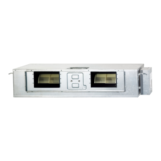
- Page 1 Duct Type Series BIG duct : AM✴✴✴FNHDCH✴ Air Conditioner installation manual imagine the possibilities Thank you for purchasing this Samsung product.
-
Page 2: Table Of Contents
Contents Safety Precautions ..................... . . 3 Accessories . -
Page 3: Safety Precautions
Safety Precautions WARNING • Cancer and Reproductive Harm - www.P65Warnings.ca.gov. The following safety precautions must be taken when using your air conditioner. • Risk of electric shock can cause injury or death. • Disconnect all remote electric power supplies before servicing, installing or cleaning. WARNING •... - Page 4 Safety precautions Power supply line or circuit breaker If the power cable of this air conditioner is damaged, it must be replaced by service agent or similarly qualified persons in order to avoid a hazard. The unit must be plugged into an independent circuit if applicable or connect the power cable to the auxiliary circuit breaker.
-
Page 5: Accessories
Accessories The following accessories are supplied with the indoor unit. The type and quantity may differ depending on the specifications. User's manual Installation manual Pattern sheet Insulation cover pipe in Insulation cover pipe out Pipe insulation (A) Pipe insulation (B) Cable tie Flexible hose Clamp hose... -
Page 6: Selecting The Installation Location
Selecting the Installation Location Indoor Unit There must be no obstacles near the air inlet and outlet. Install the indoor unit on a ceiling that can support its weight. Maintain sufficient clearance around the indoor unit. Make sure that the water dripping from the drain hose runs away correctly and safely. The indoor unit must be installed in this way, that they are out of public access. - Page 7 Insulation Guide Back Back Front Front Thickness: more than 10 mm(0.39 inch) mm(inch) Indoor Unit Front/Back Insulate the front and back side in proper 1240x470x1040 400x190 1240x1040 470x1040 470x1040 size at the same time when insulating the (48.8x18.5x40.9) (15.7x7.5) (48.8x40.9) (18.5x40.9) (18.5x40.9) suction duct and discharge duct.
- Page 8 Selecting the Installation Location Drawing of the indoor unit 1306(51.42) Suspension position Unit : mm(inch) 1188(46.77) Air inlet duct flange 140X8=1120(44.09) 140X8=1120(44.09) 1188(46.77) Air outlet duct flange 1240(48.82) 660(25.98) 647(25.47) 598(23.54) Discharge side Suction side Name Description ① Liquid pipe connection ø9.52(3/8") ②...
-
Page 9: Indoor Unit Installation
Indoor Unit Installation It is recommended to install theY-joint before installing the indoor unit. 1. Place the pattern sheet on the ceiling at the spot where you want to install the indoor unit. • Since the diagram is made of paper, it may shrink or stretch slightly due to temperature or humidity. -
Page 10: Purging The Unit
Purging the Unit On delivery, the indoor unit is loaded with inert gas. All this gas must therefore be purged before connecting the assembly piping. To purge the inert gas, proceed as follows. Unscrew the pinch pipe at the end of each refrigerant pipe. Wet cloth Result : All inert gas escapes from the indoor unit. -
Page 11: Cutting/Flaring The Pipes
Cutting/Flaring the Pipes 1. Make sure that you prepared the required tools. (pipe cutter, reamer, flaring tool and pipe holder) 2. If you want to shorten the pipe, cut it using a pipe cutter ensuring that the cut edge remains at 90° with the side of the pipe. -
Page 12: Performing Leak Test & Insulation
Performing leak test & insulation Leak test LEAK TEST WITH NITROGEN (before opening valves) In order to detect basic refrigerant leaks, before recreating the vacuum and recirculating the R-410A, it’s responsibility of installer to pressurize the Leak check whole system with nitrogen (using a pressure regulator) at a pressure above 4.1 MPa(594.7 psig) (gauge). - Page 13 5. Select the insulation of the refrigerant pipe. Insulate the gas side and liquid side pipe referring to the thickness according to the pipe size. Indoor temperature of 30 °C(86 ˚F) and humidity of 85 % is the standard condition. If the pipe is installed in a high humidity condition, use one grade thicker insulation by referring to the table below.
- Page 14 Performing leak test & insulation Refrigerant pipe before EEV kit and MCU or without EEV kit and MCU You can contact the gas side and liquid side pipes but the pipes should not be pressed. Insulation When contacting the gas side and gas side pipe, use 1 grade thicker Insulation insulation.
-
Page 15: Drain Pipe And Drain Hose Installation
Drain pipe and drain hose installation Care must be taken when installing the drain hose for the indoor unit to ensure that any condensate water is correctly drained outside. The drain hose can be installed to the right or left side of the base pan. 1. - Page 16 Drain pipe and drain hose installation Drain pipe Connection Without the drain pump 1. Install horizontal drain pipe with a slope of 1/100 or more and fix it by hanger space of 1.0~1.5 m(3.29~4.92'). 2. Install U-trap at the end of the drain pipe to prevent a nasty smell to reach the indoor unit. 3.
- Page 17 Centralized Drainage Without the drain pump 1. Install horizontal drain pipe with a slope of 1/100 or more and fix it by hanger space of 1.0~1.5 m(3.29~4.92'). 2. Install U-trap at the end of the drain pipe to prevent a nasty smell to reach the indoor unit. Horizontal drainpipe more than 1/100 slope Ceiling With the drain pump...
- Page 18 Drain pipe and drain hose installation Power and communication cable connection 1. Before wiring work, you must turn off all power sources. 2. Indoor unit power should be supplied through the breaker ( ELCB or MCCB+ELB ) separated by the outdoor power. ELCB: Earth Leakage Circuit Breaker MCCB: Molded Case Circuit Breaker ELB: Earth Leakage Breaker...
-
Page 19: Wiring Work
Wiring work Selecting compressed ring terminal Silver solder mm(inch) Norminal dimensions for cable [mm (inch 1.5 (0.002") 2.5 (0.003") 4 (0.006") Norminal dimensions for screw [mm(inch)] 4 (0.15") 4 (0.15") 4 (0.15") 4 (0.15") 4 (0.15") Standard dimension [mm(inch)] 6.6 (0.25") 8.0 (0.31") 6.6 (0.25") 8.5 (0.33") 9.5 (0.37") Allowance [mm(inch)] ±0.2 (±0.007") - Page 20 Wiring work Decide the power cable specification and maximum length within 10 % power drop among indoor units. Coef×35.6×Lk×ik ) < 10 % of input voltage[V] ∑( 1000×Ak • coef : 1.55 • Lk : Distance among each indoor unit[m], Ak : Power cable specification[mm (inch )], ik : Running current of each unit[A] Example of Installation...
- Page 21 2. As shown in the figure, peel off the shields from the rubber and wire of the Power cable power cable. - Peel off 20 mm of cable shields from the pre-installed tube. • For information about the power cable specifications for indoor and (Unit: mm) outdoor units, refer to the installation manual.
- Page 22 Wiring work • Make sure that the connection parts are not exposed to outside. • Be sure to use insulation tape and a contraction tube made of approved reinforced insulating materials that have CAUTION the same level of withstand voltage with the power cable. (Comply with the local regulations on extensions.) •...
-
Page 23: Setting An Indoor Unit Address And Installation Option
Setting an indoor unit address and installation option Set the indoor unit address and installation option with remote controller option. Set the each option separately since you cannot set the ADDRESS setting and indoor unit installation setting option at the same time. You need to set twice when setting indoor unit address and installation option. - Page 24 Setting an indoor unit address and installation option Option setting Status 1. Setting SEG2, SEG3 option Press Low Fan button( ∨ ) to enter SEG2 value. Press High Fan button( ∧ ) to enter SEG3 value. Each time you press the button, will be selected in rotation.
- Page 25 Option setting Status 12. Setting Cool mode Press Mode button to be change to Cool mode in the OFF status. 13. Setting SEG16, SEG17 option Press Low Fan button( ∨ ) to enter SEG16 value. Press High Fan button( ∧ ) to enter SEG17 value. Each time you press the button, will be selected in rotation.
- Page 26 Setting an indoor unit address and installation option Step 3. Check the option you have set After setting an option, press button to check whether the option code you input is correct or not. Step 4. Input option Press the operation button with the direction of remote control for set.
- Page 27 Setting an indoor unit address (MAIN/RMC/MCU) 1. Check whether power is supplied or not. - When the indoor unit is not plugged in, there should be additional power supply in the indoor unit. Indoor Unit 1(L) 2. The panel(display) should be connected to an indoor unit to receive 2(N) option.
- Page 28 Setting an indoor unit address and installation option Setting an indoor unit installation option (suitable for the condition of each installation location) 1. Check whether power is supplied or not. - When the indoor unit is not plugged in, there should be additional power supply in the indoor unit.
- Page 29 * The output of hot coil terminal is AC 220 V / 230 V (The same as Indoor Unit’s input Power) 1(L) 2(N) COM1 COM2 OUTDOOR Wire Remote DC 12 V COMMUNICATION Controller POWER COIL The external output of SEG15 is generated by MIM-B14 connection. (Refer to the manual of MIM-B14.) ■...
- Page 30 Setting an indoor unit address and installation option Option SEG7 SEG8 SEG9 SEG10 SEG11 SEG12 EEV Step when Explanation PAGE Use of drain pump Use of hot water heater heating stops Indication Details Indication Details Indication Details Indication Details Disuse Disuse Default Use (*3)
- Page 31 • If Fan is set to off for cooling only indoor unit by setting the SEG9=3 or SEG15=3, you need to use an external sensor or wired remote controller sensor to detect indoor temperature exactly. (*5) When indoor unit is in cooling or DRY mode, The output signal is “ON” (*6) For free cooling control, economizer controller is required.
- Page 32 Setting an indoor unit address and installation option ■ 05 series installation option(Detailed) Option No. : 05XXXX-1XXXXX-2XXXXX-3XXXXX Option SEG1 SEG2 SEG3 SEG4 SEG5 SEG6 (When setting SEG3) Use of Auto Change Over (When setting SEG3) (When setting SEG3) Standard for mode Explanation PAGE MODE...
- Page 33 Option SEG13 SEG14 SEG15 SEG16 SEG17 SEG18 Explanation Control variables when using hot water / external heater (*4) Details Indication Details Indication Set temp. for heater On/Off Delay time for heater On At the same time as thermo on No delay At the same time as thermo on 10 minutes At the same time as thermo on...
- Page 34 Setting an indoor unit address and installation option SEG 3, 4, 5, 6, 8, 9 additional information When the SEG 3 is set as "1" and follow Auto Change Over for HR only operation, it will operate as follows. Standard temp. for Heating Temp.
- Page 35 Changing a particular option You can change each digit of set option. Option SEG1 SEG2 SEG3 SEG4 SEG5 SEG6 Tens digit of option SEG Unit digit of option SEG Explanation PAGE MODE Option mode to change Changed value to change to change Remote Controller...
-
Page 36: Setting Temperature Control Of Discharge Air
Setting temperature control of discharge air 1. Use of “Temperature control of discharge air” or target temperature of discharge air in cooling/heating can be set with the service mode of a wired remote controller. (Refer to the installation manual of a wired remote controller.) 2. -
Page 37: Troubleshooting
Troubleshooting Detection of errors If an error occurs during the operation, an LED flickers and the operation is stopped except the LED. If you re-operate the air conditioner, it operates normally at first, then detect an error again. LED Display on the receiver & display unit LED Display LED Display Error... - Page 38 Troubleshooting LED Display Error Abnormal conditions code 1. COND mid sensor is detached E241 2. Refrigerant leakage (2nd detection) E554 3. Abnomally high temperature on Cond (2nd detection) E450 4. Low pressure s/w (2nd detection) E451 5. Abnomally high temperature on discharged air on outdoor E416 unit (2nd detection) 6.
-
Page 39: Option Table
Option table E.S.P(External Static Pressure)setting for phase control motor With its phase control motor, you can adjust the indoor unit fan speed depending on the installation condition. If the external static pressure is high so that the duct becomes longer or if the external static pressure is low so that the duct becomes shorter, adjust the fan speed by referring the following table. - Page 40 DB68-03807A-04...
Need help?
Do you have a question about the Duct Type Series and is the answer not in the manual?
Questions and answers