Table of Contents
Advertisement
Quick Links
T6634-TA10 TE20 TF20-9JS0 Series Fan Coil Thermostat (ON/OFF) - Installation Instructions
T6634-TA10 TE20 TF20-9JS0
T6000
T6000
HVAC
/
T6000
T6000
T6000
75x75x 35mm
:
T6000
PWT2.5X5X5.5
)
601V-B01A-NB Rev 2-Issue Date 09 2012
601V-B01A-NB Rev 2-Issue Date 09 2012
(
/
LCD
/
M/
On/Off
3 )
(
Mx5
(
Cover
PCB
This document is subject to change without notice
) -
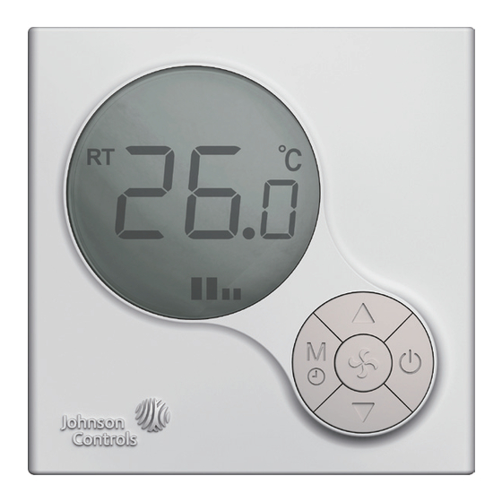
1: T6634
Figure 1: T6634 LCD Digital Fan Coil Thermostat
Application
T6000 LCD Digital Fan Coil Thermostats
The T6000 Digital Fan Coil Thermostats feature local temperature control within fan coil
operations. Select the temperature scale and setpoint, the mode, and the differential values
to control the Heating, Ventilating, and Air Conditioning (HVAC) system that maintains the
desired room temperature. The optional Occupied/Unoccupied feature saves energy by
enlarging the acceptable temperature range.
T6000 features with Backlit Liquid Crystal Display (LCD), one Mode/Timer (M/ ) selection
button, two Adjustment buttons ( & ), one Fan Speed ( ) selection button and one On/Off
( ) button.
30mm.
70mm.
Retention Screw
Hinge Hook
Installation
Install the T6000 where the occupant can read the display and adjust the setpoint easily.
Situate the thermostat where the temperature is representative of the general room
conditions. Avoid installing the T6000 near cold or warm air drafts, radiant heat, on an
outside wall, or in direct sunlight.
Mounting
Mount the T6000 Series thermostat to a 75x75x35mm standard electrical wallbox. (See
Figure 3 )
Follow the instruction in removing the base and then proceed to the wall box Mounting and
the Wiring sections.
Note:
All T6000 Series models require two No. Mx5 mounting screws (Included in the box,
screw PWT2.5X5X5.5 is required if missing).
Wall Box
Retention Screw
Base
Field Cabling
Wall Box 2 MX5
Mounting Screw
Wafer
Connector with 12cm 20AWG PVC Cable
12cm
,
"Wafer"
, 20AWG PVC
Removing the Base
Loosen (Do Not Remove) the single Phillips-Head retaining screw at the top of the case to
swing the thermostat slightly away from the base. By gently sliding it forward, the thermostat
hinge hooks come away from the hinge slots at the bottom of the mounting base to provide
easy access for mounting and wiring. The Printed Circuit Board (PCB) is attached inside the
cover with connection pin near the middle of the mounting base.
2: T6634
Figure 2: T6634 Series Thermostat Dimensions (mm)
,
MX5
3:
Figure 3: Exploded View
(mm)
1
Advertisement
Table of Contents

Subscribe to Our Youtube Channel
Related Manuals for Johnson Controls T6000 Series


Summary of Contents for Johnson Controls T6000 Series
- Page 1 Follow the instruction in removing the base and then proceed to the wall box Mounting and the Wiring sections. T6000 Note: All T6000 Series models require two No. Mx5 mounting screws (Included in the box, PWT2.5X5X5.5 screw PWT2.5X5X5.5 is required if missing). Wall Box...
- Page 2 Proceed to the Wiring section for the correct configuration for the application and units. Wiring Wire the unit according to the instructions for the appropriate model. Note: When wiring the T6000 Series Digital Fan Coil Thermostat, use wire nuts to finish and T6000 isolate each connection.
-
Page 3: Troubleshooting
( ) button switches through the sequence. The selected icon flashes, the icon is confirmed after 3 seconds. The icon will be displayed on the screen after confirmed. Note: Every time switch On the T6000 Series thermostat, the low speed fan will be initiated. T6000 These soft-start feature prevent high startup current, while provides energy saving to electricity consumption. - Page 4 T6634-TA10 TE20 TF20-9JS0 Series Fan Coil Thermostat (ON/OFF) - Installation Instructions T6634-TA10 TE20 TF20-9JS0 IMPORTANT Use this T6000 Series Line Voltage Fan Coil Thermostat only as an operating T6000 T6000 control. Where failure of malfunction of the T6000 Series Thermostat could lead to personal injury or property damage to the controlled equipment or other property, additional precautions must be designed into the system.
Need help?
Do you have a question about the T6000 Series and is the answer not in the manual?
Questions and answers