Advertisement
Quick Links
TEC22x2-3 L
ON
Installation Instructions
Applications
The TEC2202-3 non-programmable and
TEC2262-3 programmable thermostats are
L
W
® networked devices that provide control of
ON
ORKS
heat pump equipment. The technologically advanced
TEC22x2-3 thermostats feature a Building Automation
System (BAS) L
W
ON
ORKS
capability that enables remote monitoring and
programmability for efficient space temperature control.
IMPORTANT: The TEC22x2-3 thermostat is
intended to provide an input to equipment under
normal operating conditions. Where failure or
malfunction of the thermostat could lead to personal
injury or property damage to the controlled
equipment or other property, additional precautions
must be designed into the control system.
Incorporate and maintain other devices such as
supervisory or alarm systems or safety or limit
controls intended to warn of, or protect against,
failure or malfunction of the thermostat.
North American Emissions Compliance
United States
This equipment has been tested and found to comply
with the limits for a Class A digital device pursuant to
Part 15 of the FCC Rules. These limits are designed to
provide reasonable protection against harmful
interference when this equipment is operated in a
commercial environment. This equipment generates,
uses, and can radiate radio frequency energy and, if
not installed and used in accordance with the
instruction manual, may cause harmful interference to
radio communications. Operation of this equipment in a
residential area is likely to cause harmful interference,
in which case the user will be required to correct the
interference at his/her own expense.
Canada
This Class (A) digital apparatus meets all the
requirements of the Canadian Interference-Causing
Equipment Regulations.
W
® Networked Heat Pump Thermostat
ORKS
network communication
TEC22x2-3 L
ON
Cet appareil numérique de la Classe (A) respecte
toutes les exigences du Règlement sur le matériel
brouilleur du Canada.
Installation
Location Considerations
Locate the TEC22x2-3 thermostat:
•
on a partitioning wall, approximately 5 ft (1.5 m)
above the floor in a location of average
temperature
•
away from direct sunlight, radiant heat, outside
walls, behind doors, air discharge grills, stairwells,
or outside doors
•
away from steam or water pipes, warm air stacks,
unconditioned areas (not heated or cooled), or
sources of electrical interference
Note: Allow for vertical air circulation to the
TEC22x2-3 thermostat.
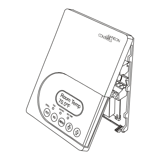
To install the thermostat:
1. Use a Phillips-head screwdriver to remove the
security screw on the bottom of the thermostat
cover.
2. Pull the bottom edge of the thermostat cover and
open the thermostat as illustrated in Figure 1.
Figure 1: Removing the Thermostat Cover
W
® Networked Heat Pump Thermostat Installation
ORKS
Part No. 24-9890-471, Rev. —
Issued September 8, 2006
Instructions
1
Advertisement

Related Manuals for Johnson Controls TEC22 2-3 LonWorks Series


Summary of Contents for Johnson Controls TEC22 2-3 LonWorks Series
- Page 1 TEC22x2-3 L ® Networked Heat Pump Thermostat ORKS Installation Instructions Part No. 24-9890-471, Rev. — Issued September 8, 2006 Applications Cet appareil numérique de la Classe (A) respecte toutes les exigences du Règlement sur le matériel The TEC2202-3 non-programmable and brouilleur du Canada.
- Page 2 3. Carefully pull the locking tabs on the right side of 8. Swing the PCB back to the right and carefully snap the thermostat mounting base and unlock the it into the locking tabs on the thermostat mounting Printed Circuit Board (PCB). Open the PCB to the base.
- Page 3 Note: For more details on wiring the network, refer to the Table 1: Terminal Identification (See Figure 5.) ORKS Network Layout Technical Bulletin ORKS Number Label Function (LIT-1162150). Energizes second-stage compressor 2. Carefully push any excess wire back into the wall. on a call for heating or cooling.
- Page 4 Separate 24 VAC To Auxiliary Transformer Heat Circuit Note: Use 24 VAC interface relays R1-1, R2-1, R3-1, and R4-1 R3-1 R4-1 R2-1 R1-1 (provided by the user). Heat Pump Terminal Interface Figure 7: VDC Switching Application for Heat Pumps Connecting the L Network Note: There is no polarity when connecting the ORKS...
-
Page 5: Setup And Adjustments
Setup and Adjustments Backlit Liquid Crystal Display (LCD) The TEC22x2-3 thermostat includes a 2-line, Thermostat Operation Overview 8-character backlit display. Low-level backlighting is present during normal operation, and it brightens when any user interface key is pressed. The backlight returns to low level when the thermostat is left unattended for 45 seconds. - Page 6 Configuring the TEC22x2-3 Thermostat For additional information on commissioning and configuring thermostats, adding thermostats to a The TEC22x2-3 thermostat comes from the factory Network Automation Engine (NAE), thermostat with default settings for all configurable parameters. mapping, and remote thermostat commanding, refer to The default settings are shown in Table 2.
- Page 7 Table 2: Installer Configuration Menu (Part 2 of 5) Parameter Description and Default Selection Options Appearing on Display Configuration of Digital Input 2. (None): No function is associated with an input. Default: None (Service): A Service alarm is displayed on the thermostat when the input is energized.
- Page 8 Table 2: Installer Configuration Menu (Part 3 of 5) Parameter Description and Default Selection Options Appearing on Display Heat cph Sets the maximum number of Range: 3.0 to 8.0 cycles per hour Heating cycles per hour. Default: 4.0 Cool cph Sets the maximum number of Range: 3.0 or 4.0 cycles per hour Cooling cycles per hour.
- Page 9 Table 2: Installer Configuration Menu (Part 4 of 5) Parameter Description and Default Selection Options Appearing on Display Discontinues heating operation in Range: -15°F/-26°C to 120°F/49°C adjustable in 5F°/5C° increments H lock response to the outdoor air temperature. Requires that an outdoor air temperature sensor be installed and connected.
- Page 10 Table 2: Installer Configuration Menu (Part 5 of 5) Parameter Description and Default Selection Options Appearing on Display Comf/eco Selects how the auxiliary heat is (economy) – in the heating mode: If the heat pump is not able to used. satisfy the heating setpoint, the auxiliary heat is energized to satisfy the setpoint only when the temperature has dropped 2F°/1C°...
-
Page 11: Operation
Operation 2. Press the YES key to resume the programmed schedule. Programming/Operating the TEC22x2-3 The thermostat returns to the Status Display Menu. Thermostat Once the thermostat is configured via the Installer Entering Permanent Temperature Setpoints Configuration Menu, its operating parameters can be The first prompt appearing in the Main User Menu of programmed via the Main User Menu. - Page 12 Table 3: Entering Permanent Temperature The setpoint reverts to the Permanent Temperature Setpoints (Part 2 of 2) Setpoint. Thermostat Description Selecting the System Mode Display The thermostat has four system modes: Press the UP/DOWN arrow keys to • Automatic Mode (auto): Automatic changeover set the temperature.
- Page 13 Selecting Schedule (TEC2262-3 Only) Table 4: Programming the Daily Schedule – Two-Event (Part 2 of 2) Programming the Daily Schedule – Two-Event Thermostat Description The schedule-setting menu is used to enter the Display occupied or unoccupied states for each day of the Press the UP/DOWN arrow keys to week.
- Page 14 To set the time schedule for a four-event schedule, Table 5: Programming the Daily Schedule – follow the steps in Table 5. See Table 6 for an example Four-Event (Part 2 of 2) of a four-event office schedule. Thermostat Description Table 5: Programming the Daily Schedule –...
- Page 15 Table 6: Four-Event Office Schedule Event 1 Event 2 Event 3 Event 4 Occupied Unoccupied Occupied 2 Unoccupied 2 Event Cool Heat Cool Heat Cool Heat Cool Heat 72°F 70°F 80°F 62°F 72°F 70°F 80°F 62°F (22°C) (21°C) (27°C) (17°C) (22°C) (21°C) (27°C)
-
Page 16: Repair Information
Repair Information All the accessories in Table 7 include mounting If the TEC22x2-3 thermostat fails to operate within its hardware; contact the nearest Johnson Controls® specifications, see Table 8 for troubleshooting details representative to order any of these parts. and Table 9 for display messaging. For a replacement... - Page 17 Table 8: Troubleshooting Details (Part 2 of 3) Symptom Cause Solution(s) Thermostat does Wrong mode Select cooling mode. not call for cooling selected Thermostat in Select Override to force the thermostat Occupied cooling setpoint. Unoccupied mode Anticycle delay Wait, the anticycling period must end before the equipment can start. active Cooling setpoint is Lower the cooling setpoint.
-
Page 18: Technical Specifications
Table 8: Troubleshooting Details (Part 3 of 3) Symptom Cause Solution(s) Heat Pump does Wrong mode Select Heating mode. not operate in selected heating mode Thermostat in Select Override to force the thermostat Occupied heating setpoint. Unoccupied mode Heating setpoint is Raise the Heating setpoint. - Page 19 The performance specifications are nominal and conform to acceptable industry standards. For application at conditions beyond these specifications, consult the local Johnson Controls office. Johnson Controls, Inc. shall not be liable for damages resulting from misapplication or misuse of its products.
Need help?
Do you have a question about the TEC22 2-3 LonWorks Series and is the answer not in the manual?
Questions and answers