Nederman FlexPAK 800 Setting Manual
Compact dust collectors
Hide thumbs
Also See for FlexPAK 800:
- Installation and service manual (34 pages) ,
- User manual (358 pages)

Related Manuals for Nederman FlexPAK 800


Summary of Contents for Nederman FlexPAK 800
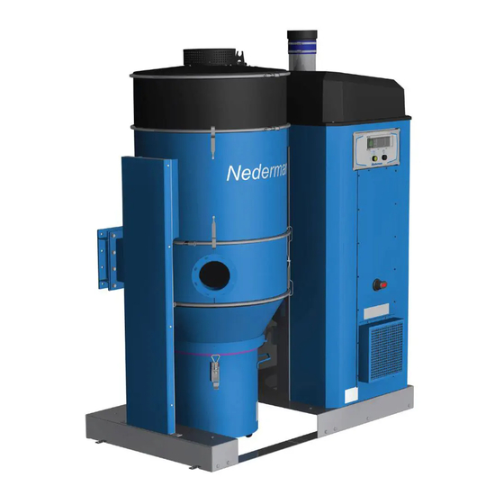
- Page 1 PLC Settings Manual Compact dust collectors FlexPAK 800/1000 All Models (Software #2168209-X) Original PLC Settings Manual PLC SETTINGS MANUAL 2018-10-16 2130066(01)
-
Page 2: Flexpak
FlexPAK 800/1000... - Page 3 FlexPAK 800/1000 Figures ..............................English ..............................
-
Page 4: Table Of Contents
FlexPAK 800/1000 Figures FlexPak Hi Vacum Unit TimeTo Service FlexPAK O 2000 Hours NEDERMAN FLEXPAK Standby Waiting For Pilot Signal Mo 15:33 Standby Pilot signal OFF Pilot signal On Running Running DIRTm 00:00 s OTTmr 00:00 h P = -5... - Page 5 FlexPAK 800/1000...
- Page 6 FlexPAK 800/1000...
- Page 7 ....................................2 Safety ....................................General ................................3 PLC messages ................................Status messages ............................3.1.1 Nederman FlexPAK Off (Off mode) ..................3.1.2 FlexPAK Standby (Standby mode) ..................3.1.3 Running (Running mode) ......................3.1.4 FlexPAK Idling (Idling mode) ...................... 3.1.5 Filter Cleaning ...........................
- Page 8 FlexPAK 800/1000 4.2.6 FltClean ................................. 4.2.7 DIR_Time ..............................4.2.8 Weekly Timer ............................4.2.9 Presep ................................4.2.10 MFDPS-Wr ..............................4.2.11 MFDPS-FC ..............................4.2.12 BLI-Empt ..............................4.2.13 BLI-Wr ................................. 4.2.14 AEBTme ..............................4.2.15 BinOpnTm ..............................4.2.16 CFDPS-Al ..............................4.2.17 TVFDAdv ..............................4.2.18 PSCFlush ..............................
-
Page 9: Preface
Nederman original spare parts and accessories. Contact the nearest authorized distributor or Nederman for advice on technical service and obtaining spare parts. If there are any damaged or missing parts when the product is delivered, notify the carrier and the local Nederman representative immediately. -
Page 10: Timeto Service 2000 Hours
High vacuum. A high vacuum system creates a powerful suction that may cause serious eye injury or hearing impairment. Persons who will be using FlexPAK 800/1000, or may come in contact with FlexPAK 800/1000, are to be informed about this risk. -
Page 11: Air Temp
FlexPAK 800/1000 3.1.3 Running (Running mode) The unit in Running mode. The pump motor is on and the unit generates a vacuum. The FCV is closed. The current vacuum of the unit is shown on the display, for example, -20 kPa. -
Page 12: Esc Ok
FlexPAK 800/1000 3.1.8 Close Upper Slide Valve V12 The message appears when the TVFD Upper Solenoid Valve is expected to close. The timer is set with TVFDC-Al, see Section ‘4.2.26 TVFD-Al-Tmr’. If the timer elapses, the ‘TVFD Alarm! Upper Slide Not Closed is activated. This message is only shown when TVFD advanced is activated. -
Page 13: Hi Vacuum Unit
FlexPAK 800/1000 3.1.12 Isolation Damper Closing Duct When the parameter (Softkey, DuctIsoDamp = On), FlexPak is configured to control a damper that separates the filter from the factory’s channel system. The message appears before filter cleaning starts. The display shows the time delay set for opening the damper after filter cleaning. -
Page 14: Warning! Main Filter Clogged
FlexPAK 800/1000 3.2.2 Warning! Main Filter Clogged This Warning is only shown when the Main Filter Delta Pressure Switch (MFDPS) is installed. This message is displayed if the Differential Pressure switch “DP switch” is installed and the Dp switch detects a high differential pressure across the filter. -
Page 15: Alarms
FlexPAK 800/1000 Alarms If an alarm is activated, the unit goes into Off mode until the problem is corrected. If an alarm message is displayed in the PLC display, the light in the Standby/Running button flashes one second on, one second off. This 1/1 on/off sequence continues until the problem is corrected and the alarm reset. -
Page 16: Low Pressure Or Duct Isolation Released
FlexPAK 800/1000 3.3.4 Low Pressure or Duct Isolation Released The Compressed Air Switch (CAS) indicates that the compressed air pressure is too low. Or, there is a duct isolation valve connected to the system that has released and isolated FlexPAK from the duct system. Check the isolation valve release sensor, released isolation vale = open electrical circuit to input on PLC. -
Page 17: Alarm! Control Filter Clogged
FlexPAK 800/1000 3.3.8 Alarm! Control Filter Clogged The control filter is clogged and needs to be cleaned. It generally indicates a problem with the main filter, or the control filter has been used too long and needs to be replaced. This alarm is activated when CFDPS-Al has been activated for 5 seconds. -
Page 18: Tvfd Alarm! Lower Slide Not Closed
FlexPAK 800/1000 3.3.11 TVFD Alarm! Lower Slide Not Closed The TVFD Lower Solenoid Valve does not close while the dust bin is being emptied. TVFDC- Al has expired. It can be caused by the following: • The lower slide valve has not been activated as it should. -
Page 19: Alarm! Dustbin Full
FlexPAK 800/1000 3.3.14 Alarm! Dustbin Full When a level indicator set for a time delay of 30 minutes is activated, then when the delay has elapsed a message “Alarm! Dustbin Full” appears on the display and the unit is stopped. -
Page 20: Plc Settings
FlexPAK 800/1000 PLC settings The following PLC displays show the different settings that can be configured for the unit. Find a parameter and set its value Stop > FlexPak Program > Hi Vacuum Unit Setup > Thu 10:45 Network >... -
Page 21: Parameter Settings
FlexPAK 800/1000 Parameter settings 4.2.1 Adjust the time and date FlexPak Stop > Hi Vacuum Unit Program > Setup > Thu 10:45 Network > 2018-02-01 Time To Service Diagnostics > 2000 hours Msg Config > Set Clock Set Clock >... -
Page 22: Set The Weekly Timer
FlexPAK 800/1000 4.2.2 Set the weekly timer Weekly timer sets the unit to “Stand By” mode and “Off Mode” at preset times. If the pilot signal “PS” is active and the Vacuum unit is in Standby mode, the unit starts. -
Page 23: T > 12:00M
FlexPAK 800/1000 Weekend or second shift setting D3 = _ _ _ _ _ SS: Default setting; Saturday and Sunday. On3 = _ _: Default setting Time the unit set to ‘Stand By’ on chosen D3 WeekTmr Off2 = -- : -- days. -
Page 24: Cooltmr
FlexPAK 800/1000 4.2.5 CoolTmr CoolTmr cools the unit by open Cleaning Valve V1 “SCV” to cool the vacuum pump. The CoolTmr timer function is started by CoolTmp. When the fan’s outgoing air temperature is over the CoolTmp threshold, “On=97”, CoolTmr is activated and opens Cleaning Valve V1 (SCV).It keeps the valve open for (TH=X seconds),... -
Page 25: Presep
FlexPAK 800/1000 4.2.9 Presep Menu for activating automatic emptying of two preseparators. This cannot be used together with TVFD. Presep activates PresepTm to control the TVFD Solenoid Upper Valve (SUV). It uses BinOpnTm to control the TVFD Solenoid Lower Valve (SLV). -
Page 26: Bli-Wr
FlexPAK 800/1000 4.2.13 BLI-Wr Menu for setting the delay time for the Bin Level Indicator warning message. When the BLI signal disappears, the BLI-Wr timer is activated. When the timer elapses, the message ‘Warning! Dustbin Full’ is activated, see Section ‘3.2.3 Dustbin Full’. -
Page 27: Pscflush
FlexPAK 800/1000 4.2.18 PSCFlush Menu for activating flushing of the duct system. When ‘Switch=Off’, flushing is timer controlled. When ‘Switch=On’, flushing is contolled by the pilot signal; flushing takes place when the pilot signal dissapears. See Sections ‘4.2.32 PSIFC’ and ‘4.2.34 FlushTmr’. -
Page 28: Ottmr
FlexPAK 800/1000 4.2.23 OTTmr Menu for setting the overtime timer. If the unit needs to be used after the weekly timer has expired, the unit can be turned on for a set number of hours by pressing the external standby button. When the OTTmr expires, the machine goes back into Off mode. -
Page 29: Cooltmp
FlexPAK 800/1000 4.2.25 CoolTmp Menu for setting CoolTmp. See section ‘4.2.5 CoolTmr’. The default settings for CoolTmp: On=97: The default temperature limit that is set to open Cleaning Valve CoolTmp V1 “SCV”. The default setting is 97°C (207ºF). On = 97... -
Page 30: Vac_Low
FlexPAK 800/1000 4.2.28 Vac_Low Menu for setting the warning level for Low vacuum in the system. When the vacuum level is above the set limit value, a warning message appears on the display. The warning message is delayed to filter messages that would otherwise be activated by temporary pressure changes in the system. -
Page 31: Vaclotm
FlexPAK 800/1000 4.2.31 VacLoTm Delay Timer for “Warning! Low Vacuum”, see section ‘3.2.5 Warning Low Vacuum’ and section ‘4.2.28 Vac_Low’. This timer delays showing the message “Warning! Low Vacuum “ when the vacuum is too low in the system. The timer serves as a filter to remove short-term vacuum variations in the system. -
Page 32: Fcdelay
FlexPAK 800/1000 4.2.35 FCDelay FCDesay is used in ATEX applications. This function is used to prevent the safety damper, Duct Isolation Damper, from unintentionally opening during filter cleaning. During filter cleaning, high velocity air flows out of the filter housing through the safety damper Duct Insulation Damper, which may cause it to close. -
Page 33: Bli-Alarm
FlexPAK 800/1000 4.2.38 BLI-Alarm Menu for setting the delay time for the Bin Level Indicator Alarm message. When the BLI signal disappears, the BLI-Alarm timer is activated. When the timer elapses, the Alarm message “Alarm! Dustbin Full” appears and the vacuum unit is stopped. -
Page 34: Clean Cycle
FlexPAK 800/1000 4.2.42 Clean cycle The time duration for a cleaning cycle. Tch: Vacuum building time (Charge time). Default is 3 seconds. CleanCycle Tpu: Clean pulse time. Default is 2 seconds. Tch = 03:00s Tpu = 02:00s On: Number of cleaning pulses. Default is 1 pulse. Note! Minimum value = 1. -
Page 35: Timer Settings
FlexPAK 800/1000 NOTE! Presep overrides 2 above. NOTE! If TVFDAdv is activated (Switch = On), TVFDAdv overrides 1 and 2 above. 5.2.3 Timer settings BinOpnTm TL = Delay after the upper slide starts to close before the lower slide starts to open. The default is 5 seconds. -
Page 36: Advance Tvfd Valve Settings
FlexPAK 800/1000 Advance TVFD Valve Settings 5.4.1 Hardware • TVFD (SUV) Solenoid Upper Valve (V12) • TVFD (SLV) Solenoid Lower Valve (V11) • TVFD Upper Position Sensor (UPS) monitoring slide valve (V12) • TVFD Lower Position Sensor (LPS) monitoring slide valve (V11) 5.4.2... -
Page 37: Pneumatic Filter Cleaning Valve
FlexPAK 800/1000 If there are multiple indicator lamps connected to the system, it is recommended that semiconductor LED indicators used. Pneumatic filter cleaning valve Filter cleaning button The filter cleaning button will only work when the system is in Standby mode or Running mode. -
Page 38: Atex Duct Isolation Valve Settings
FlexPAK 800/1000 If the piston does not fall down, the piston may not evacuate properly. If the incoming compressed air is disconnected, the piston should fall down allowing the lid to close the filter top opening. ATEX Duct Isolation Valve settings This is for ATEX units with the Duct Isolation Valve and Duct Isolation Damper. -
Page 39: Fcdely(T) Parameter Calculation See, Timing Diagram
FlexPAK 800/1000 Vacuum set points: • FlexPak 1000 = 20kPa • FlexPak 800 = 35kPa Closing time is Approximately 5 seconds in a 35kPa vacuum. 8.2.2 FCDely(T) Parameter Calculation See, Timing diagram 35kPa vacuum → Closing time = 5 seconds. -
Page 40: Total Filter Cleaning Sequence Time
2 + (3*3) + (2*2) + 4 = 19 seconds 8.5.1 Settings TL = Vacuum Load Time Vacuum set points FlexPak 1000 = 20kPa, FlexPak 800 = 35kPa Examples of adjustment Start the unit and activate the pilot signal (PS). Wait 6 seconds before pushing the Filter cleaning button. -
Page 41: Appendix A: Plc Setttings Protocol
FlexPAK 800/1000 Appendix A: PLC setttings protocol Copy the PLC settings protocol, fill it in and save it as a service record. PLC setting Default value Customer specific value... - Page 42 FlexPAK 800/1000 PLC setting Default value Customer specific value...
- Page 44 www.nederman.com...
Need help?
Do you have a question about the FlexPAK 800 and is the answer not in the manual?
Questions and answers