
Subscribe to Our Youtube Channel
Related Manuals for Nederman FlexPAK 800


Summary of Contents for Nederman FlexPAK 800
- Page 1 Installation and service manual Compact dust collectors FlexPAK 800/1000 Standard models Original installation and service manual INSTALLATION AND SERVICE MANUAL 2018-05-23 144838(03)
-
Page 2: Flexpak
FlexPAK 800/1000... - Page 3 FlexPAK 800/1000 Figures ..............................English ..............................
- Page 4 FlexPAK 800/1000 Figures Type Art.no Ser.no Year of manufacture AB Ph Nederman & Co SWEDEN 1670mm (66.0") 907mm (35.7") 966mm (38.0")
- Page 5 FlexPAK 800/1000...
- Page 6 FlexPAK 800/1000...
-
Page 7: Figures
FlexPAK 800/1000 SIEMENS Stop Set Param >Prg Name LOGO! 12/24RC XXXXXXX-XXXXX-XXXX... - Page 8 FlexPAK 800/1000 1643±1mm (65”)
- Page 9 FlexPAK 800/1000...
- Page 10 FlexPAK 800/1000 Min > 2.1m (83") 1.0 m (39.4")
-
Page 11: Table Of Contents
FlexPAK 800/1000 English Installation and service manual Table of contents Figures ....................................1 Preface ....................................2 Safety ....................................3 Description ..................................Function ................................Dimensions ..............................Technical data ..............................Fuses ................................... Main components ............................Connections ..............................Start and control unit .......................... -
Page 12: Preface
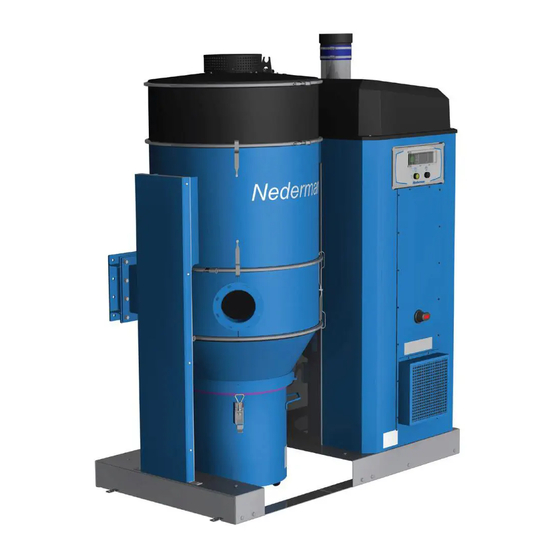
Description Function FlexPAK 800/1000 is a complete vacuum unit with a direct driven side channel fan fitted as one unit on a steel frame and a start and control unit with an integrated 24 V transformer. The unit is controlled by a frequency converter, has automatic start/stop, and automatic filter cleaning. -
Page 13: Dimensions
FlexPAK 800/1000 Automatic filter cleaning FlexPAK 800/1000 uses filter cleaning by a short blast of reversed air flow with atmospheric pressure. By the rapid opening of the Filter Cleaning Valve (FCV) located on top of the filter, a powerful blast of reversed air flow is created, efficiently dislodging dust from the filter bags, see figure 8. -
Page 14: Fuses
Never use the unit without a plastic bag. CAUTION! Risk of equipment damage. Use only Nederman original spare parts and accessories. Figure 3, 4 and 5 show the main components of the unit: Collector bin, see figure 3. Dust extractor, see figure 3. -
Page 15: Connections
FlexPAK 800/1000 Inlet silencer before fan, see figure 4. Pressure sensor, see figure 4. Acoustic enclosure, see figure 4. Compressed air supply, see figure 5. Connections NOTE! The exhaust air duct is to be routed straight and as short a distance as possible. -
Page 16: Frequency Converter
The manual for the frequency converter is enclosed. Accessories The FlexPAK 800/1000 start and control unit is prepared for the connection of Nederman accessories and customer connections. The installation of accessories, extra equipment, and functions is described in the manual for each product and according to the electrical diagrams that came with the unit. -
Page 17: Delivery Check
Check the unit for any transport damage. In case of damage or missing parts, notify the carrier and your local Nederman representative immediately. Installation requirements Prepare the location where FlexPAK 800/1000 is to be placed before installation. Consider the following when installing the unit: •... -
Page 18: Recommendations
FlexPAK 800/1000 WARNING! Explosion risk. • Do not collect material that may cause ignition or blocking. It is strictly prohibited to collect material that may undergo dangerous chemical or thermal reactions and/or self- ignite. • Some types of dust may cause a dust explosion and/or fire. Before installation, investigate whether the dust to be collected by the system constitutes a risk. -
Page 19: Outdoor Installation
The disconnecting device is to be fitted within 2–3 m from FlexPAK 800/1000 and be clearly visible from the unit. Refer to local and national standards when located outside of Europe. -
Page 20: General Requirements
FlexPAK 800/1000 NOTE! Check that the supply voltage corresponds to the data on the machine plate of the unit, see figure 1, before connecting the unit to the mains supply. NOTE! Control that TR1, see figure 5, item 2, is connected to the correct voltage range. -
Page 21: Installation
NOTE! Always disconnect the compressed air supply before any service, whether mechanical or electrical. NOTE! Contact Nederman if the frequency converter needs service. NOTE! The unit is CE-marked. Connections to the unit, initial start-up and maintenance are to be carried out according to the product manuals.. -
Page 22: Empty The Collector Bin
FlexPAK 800/1000 WARNING! Risk of personal injury. • Ensure that there is no vacuum present in the system during service. • Always disconnect the compressed air supply before any service. NOTE! Check all power conductors and protective conductors one month after installation and tighten, if required, to ensure good contact. -
Page 23: Check The Filter Cleaning Function
In any case, the bearings are to be replaced every fifth year. The bearings are a standard type. Contact Nederman or an authorized Nederman distributor for replacement of the bearings. Old grease is to be removed and new grease used. The grease is to meet the DIN 51825- K2N 40, SKF LGHP 2 or FAG Arcanol Multitop standards. -
Page 24: Frequency Converter Control Panel
The product has been designed for component materials to be recycled. Its different material types must be handled according to relevant local regulations. Contact the distributor or Nederman if uncertainties arise when scrapping the product at the end of its service life. -
Page 25: Troubleshooting
If a fault occurs which cannot be adjusted according to the following descriptions, a Nederman service technician is to be called. Tools To carry out troubleshooting, it is necessary to have a multimeter with V DC and ohm measuring capabilities. - Page 26 The cylinder and/or valve does Replace the cylinder and/or valve. not work. Dust is hard to clean, normal Contact your nearest authorized distributor or Nederman cleaning does not work. for technical advice. The cleaning interval is too short. Extend the cleaning interval.
-
Page 27: Acronyms And Abbreviations
FlexPAK 800/1000 Acronyms and abbreviations Automatic emptying of bin Auxiliary Bin level indicator Bin Level Warning indicator BLI-Wr Compressed air switch Control Filter Differential Pressure Sensor Alarm CFDPS-Al Duty/idle relay Duct isolation valve Data Unit Electromagnetic compatibility Electrically erasable programmable read-only memory... -
Page 28: Appendix A: Installation Protocol
FlexPAK 800/1000 Appendix A: Installation protocol Copy the installation protocol, fill it in and save it as a service record. For values, note the value in the result column, otherwise a tick will suffice if the item has been performed or considered. - Page 29 FlexPAK 800/1000 Control items Result Application requirements (limits) Connection – power cable, check tightness Compressed air Air lines cleaned Air pressure (6–10 bar, 87–145 PSI) Clean and dry air (ISO 8573-1, class 5) Compressed air valve Compressed air connected to unit Incoming duct –...
-
Page 30: Appendix B: Service Protocol
FlexPAK 800/1000 Appendix B: Service protocol Copy the service protocol, fill it in and save it as a service record. NOTE! If the results of the checks (for example, measured values) differ significantly from previous results, investigate more carefully. Unit No. - Page 31 FlexPAK 800/1000 Control items Result Result Result Result Clean side of filter Connecting hose vacuum Cylinder Valve plate Automatic filter cleaning, check Manual filter cleaning, check Power conductor connections and ground wires, check Vacuum limiting, check Cleaning valve, check Filter bags, visual check...
- Page 32 FlexPAK 800/1000...
- Page 34 www.nederman.com...
Need help?
Do you have a question about the FlexPAK 800 and is the answer not in the manual?
Questions and answers