Table of Contents
Advertisement
Quick Links
Read this installation manual completely to ensure proper installation, then file it with the
owner or maintenance department.
Separate parts from packaging and make sure all parts are accounted for before discarding
any packaging material. If any parts are missing, do not begin installation until you obtain
the missing parts.
Lockers should be installed in a climate-controlled environment and shielded from direct
sunlight. All lockers must be either secured against a wall or installed back-to-back (for
island configuration).
Make sure all floors and walls are clean and smooth. Remove loose impediments, such as
protruding nails, and other debris which could affect installation. The lockers must be
square AND level AND floor-supported or they will not operate properly (a locker that is
square may not be level so be sure to check both).
Review your locker layout drawings and verify the number of lockers and components
before beginning installation.
Carefully lift lockers at the base when moving and positioning. Do not drag the lockers!
Lockers and slope top components are extremely heavy and may require more than one
person to position and install.
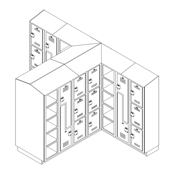
Standard lockers are shown in most illustrations. Cubby lockers and "Z" lockers are
similar and are installed in the same manner.
OPTIONAL LOCKER BASE MUST BE SQUARE AND LEVEL, AND ANCHORED TO THE
FLOOR BEFORE LOCKERS ARE INSTALLED. THE LOCKERS WILL NOT OPERATE
PROPERLY IF THE BASE IS NOT SQUARE AND LEVEL AND NOT FLOOR-SUPPORTED. A
LOCKER BASE THAT IS SQUARE MAY NOT BE LEVEL SO BE SURE TO CHECK BOTH!
FAILURE TO COMPLY WITH THESE INSTRUCTIONS MAY RESULT IN PERSONAL INJURY
AND/OR PROPERTY DAMAGE AND WILL VOID THE LOCKER WARRANTY.
Product warranties may be found under "Product Information" on our web site at
www.bradleycorp.com.
LK-INSTR-001 Rev. K; EN 07-1303
© 2007 Bradley Corporation
Page 1 of 15
10/24/07
Installation
Lenox® Lockers
Cubby & "Z" Lockers)
WARNING
P.O. Box 309, Menomonee Falls, WI 53052-0309
TEL. 1-800-BRADLEY
www.bradleycorp.com
U.S. Patent Nos. 6,685,285
6,792,661
6,793,299
7,029,078
7,223,317
7,278,695
FAX 262-253-4161
(includes
Advertisement
Table of Contents

Related Manuals for Bradley Lenox


Summary of Contents for Bradley Lenox
- Page 1 Product warranties may be found under ”Product Information” on our web site at www.bradleycorp.com. LK-INSTR-001 Rev. K; EN 07-1303 P.O. Box 309, Menomonee Falls, WI 53052-0309 TEL. 1-800-BRADLEY FAX 262-253-4161 © 2007 Bradley Corporation www.bradleycorp.com Page 1 of 15 10/24/07...
-
Page 2: Table Of Contents
Check Contents Separate all parts from packaging materials and ensure you have all parts required for installation. If any parts are missing, do not attempt to install your Lenox® Lockers until you obtain all parts. Supplies required For lockers with no base, you will need floor anchors and appropriate hardware suitable for your application. -
Page 3: Hardware List
Lenox® Lockers (includes Cubby & “Z” Lockers) Installation Hardware List (hardware provided by Bradley) FAST-LF015 1/4" x 1-3/4" Lg. Tapcon screw for base and locker mounting FAST-T349 #10 x 1/2" Lg. screw for base FAST-LF026 #6 x 1-1/2" Lg. screw for fastening corner locker to filler... -
Page 4: Locker Base Installation
Lenox® Lockers (includes Cubby & “Z” Lockers) Installation Installation Instructions Step 1: Optional Locker Base Installation IMPORTANT: Make sure the base is square AND level before anchoring to the floor (the base may be square but not level so be sure to check both). This will ensure proper locker operation. -
Page 5: Corner Filler Installation
Lenox® Lockers (includes Cubby & “Z” Lockers) Installation Installation Instructions continued . . . Step 2: Optional Corner Filler Installation NOTE: Corner fillers are designed to fill gaps in corners (a corner filler is shown in Figure 3a on page 6). They are attached to the locker with the #10-24 male and #10-24 x 1/2" female sex bolts provided. -
Page 6: Locker Installation
Lenox® Lockers (includes Cubby & “Z” Lockers) Installation Installation Instructions continued . . . Step 3: Locker Installation NOTE: Refer to your submittal layouts for proper locker position. The first locker is usually installed at a corner or at the end of a run. - Page 7 Lenox® Lockers (includes Cubby & “Z” Lockers) Installation Installation Instructions continued . . . Step 4: Corner Locker Installation 1. Drill four 3/16" dia. clearance holes 1-1/2" from the locker face through the locker box only (see Figure 4). Fasten the locker to the corner filler with the #6 x 1-1/2" screws provided.
- Page 8 Lenox® Lockers (includes Cubby & “Z” Lockers) Installation Installation Instructions continued . . . Step 5: Optional End Filler Installation BLOCKING NOTE: Fillers are designed to fill gaps between locker (provided runs. They are cut to size by the installer and attached by Installer) with 3-4 suitable fasteners supplied by the installer.
-
Page 9: Slope Top Installation
Lenox® Lockers (includes Cubby & “Z” Lockers) Installation Installation Instructions continued . . . Figure 7a Step 7a: Optional Locker Slope Top Installation NOTE: Standard 3-tier lockers are shown in Figures 7a–7e. Slope and flat tops for Cubby and “Z” lockers are similar. - Page 10 Lenox® Lockers (includes Cubby & “Z” Lockers) Installation Installation Instructions continued . . . Step 7a: Slope Top (cont’d.) 3. If a corner slope top is being installed, position that slope top first. Fit the groove of the slope top over the front edge of the locker while at the same time pressing down on the score line of the slope top as shown in Figure 7c.
-
Page 11: Flat Top Installation
Lenox® Lockers (includes Cubby & “Z” Lockers) Installation Installation Instructions continued . . . Figure 7d 2" x 2" CORNER Step 7b: Optional Locker Flat Top Installation SUPPORT BLOCKING NOTE: The flat tops are shipped in standard lengths (supplied by installer). -
Page 12: End Panel Installation
Lenox® Lockers (includes Cubby & “Z” Lockers) Installation Installation Instructions continued . . . Step 8: End Panel Installation (optional) NOTE: Optional slope top not shown in Figure 8. NOTE: The end panels can be cut to size with a panel saw if necessary. Only the front edge has a radius and should not be cut. -
Page 13: Back-To-Back Locker Installation
Lenox® Lockers (includes Cubby & “Z” Lockers) Installation Installation Instructions continued . . . Step 9: Back-To-Back Locker Installation NOTE: Back-to-back locker installation is similar to standard installation. The base sections must be square and plumb prior to installing lockers. -
Page 14: Back-To-Back Slope Top Installation
Lenox® Lockers (includes Cubby & “Z” Lockers) Installation Installation Instructions continued . . . Step 10: Back-To-Back Locker Slope Top Installation NOTE: Mounting strips will be 54" maximum length. Color of strips may vary. 1. Drill 3/16" dia. clearance holes through the top of the installed lockers, making sure that the holes are located 1-1/4"... -
Page 15: Island End Panel Installation
Lenox® Lockers (includes Cubby & “Z” Lockers) Installation Installation Instructions continued . . . #8 x 1-1/4" SCREW (FAST-LF041) Figure 10b Step 11: Island End Panel Installation 1. Drill ten 3/16" dia. holes through each of the exposed locker sides where the end panel is to be attached.
Need help?
Do you have a question about the Lenox and is the answer not in the manual?
Questions and answers