Table of Contents
Advertisement
Advertisement
Table of Contents

Related Manuals for North Star NSLA1683066


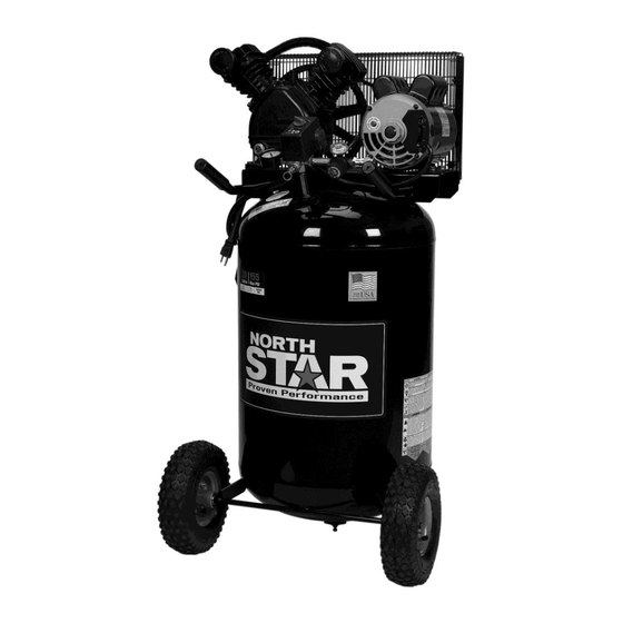
Summary of Contents for North Star NSLA1683066
- Page 1 30-Gallon Electric Air Compressor Owner’s Manual WARNING: Read carefully and understand all ASSEMBLY AND OPERATION INSTRUCTIONS before operating. Failure to follow the safety rules and other basic safety precautions may result in serious personal injury. Item #75859 READ & SAVE THESE INSTRUCTIONS...
- Page 2 ® Thank you very much for choosing a NorthStar product! For future reference, please complete the owner’s record below: Serial Number/Lot Date Code: ________________________________ Purchase Date: ____________________________________________ Save the receipt, warranty, and this manual. It is important that you read the entire manual to become familiar with this product before you begin using it.
-
Page 3: Table Of Contents
Table of Contents Intended Use ............................5 Packaging Contents ..........................5 Technical Specifications ........................5 Safety Signal Words ..........................5 Important Safety Information ....................... 6 Specific Operation Warnings ....................... 9 Main Parts of Compressor ......................... 10 Hot Surfaces ............................11 Assembly ............................. - Page 4 Pump Oil............................... 22 Compressor Pump Oil ........................22 Checking Oil ........................... 22 Changing Oil ........................... 22 Belt Replacement / Belt Tension / Motor Pulley & Flywheel Adjustment ........23 Belt Replacement ........................... 23 Adjusting Belt Tension ........................24 Motor Pulley/Flywheel Alignment ....................24 Air Compressor Pump Intake and Exhaust Valves ................
-
Page 5: Intended Use
• Air Compressor Isolator C-Channel Vibration Pads (2) • • Owner’s Manual Compressor Insert Sheet Technical Specifications Property Specification Model NSLA1683066 Weight 165 lb. (75 kg) 48” Height 24.12” Width Running HP Tank Capacity 30 Gallons Voltage/Amps/Phase 120/240 Volts / 15/7.5 Amps / 1 Phase... -
Page 6: Important Safety Information
Important Safety Information ⚠WARNING • Read and understand all instructions. Failure to follow all instructions may result in serious injury or property damage. • The warnings, cautions, and instructions in this manual cannot cover all possible conditions or situations that could occur. Exercise common sense and caution when using this tool. Always be aware of the environment and ensure that the tool is used in a safe and responsible manner. - Page 7 to handle the product. • Be aware of all power lines, electrical circuits, water pipes, and other mechanical hazards in your work area. Some of these hazards may be hidden from your view and may cause personal injury and/or property damage if contacted. •...
- Page 8 application. • Do not overreach. Keep proper footing and balance at all times. • Remove keys or wrenches before connecting the tool to an air supply, power supply, or turning on the tool. A wrench or key that is left attached to a rotating part of the tool may cause personal injury. •...
-
Page 9: Specific Operation Warnings
• To provide proper ventilation for cooling, the compressor must be kept a minimum of 12 inches (31 cm) from the nearest wall, in a well–ventilated area. • Fasten the compressor down securely if transporting is necessary. Pressure must be released from the tank before transporting. -
Page 10: Main Parts Of Compressor
Main Parts of Compressor Figure A Components Safety Valve: This valve is designed to prevent system failures by relieving pressure from the system when the compressed air reaches a predetermined level. The valve is preset by the manufacturer and must not be removed or modified in any way. Tank Pressure Gauge: The tank pressure gauge indicates the reserve air pressure in the tank. -
Page 11: Hot Surfaces
Components Motor Overload Protector: The motor has a thermal overload protector. If the motor overheats for any reason, the overload protector will shut off the motor. The motor must be allowed to cool down before restarting. To restart: Set the Auto/Off switch to OFF (O) and unplug unit. Allow the motor to cool. -
Page 12: Assembly
Assembly ⚠WARNING • This compressor was shipped with oil in the pump crankcase. Check oil before operating the air compressor. Unpack the air compressor. Inspect the unit for damage. If the unit has been damaged in transit, contact the carrier and complete a damage claim. Do this immediately because there are time limitations to damage claims. -
Page 13: Disconnecting Hoses
Disconnecting Hoses 1. Ensure regulated pressure gauge reads 0 PSI. 2. Remove hose from air outlet. Installation Lubrication and Oil The air compressor pump was filled WITH oil at the manufacturer. Check air compressor pump oil level before operating unit. See the Compressor Pump Oil section under Pump Oil. Compatibility Air tools and accessories that are run off the compressor must be compatible with petroleum-based products. -
Page 14: Wiring Instructions
Wiring Instructions A qualified electrician needs to know the following before wiring: 1. The amperage rating of the electrical box should be adequate. Refer to the Technical Specifications (page 4) for this information. 2. The supply line should have the same electrical characteristics (voltage, cycle, phase) as the motor. Refer to the motor nameplate, on the side of motor, for this information. -
Page 15: Extension Cords
Extension Cords ⚠WARNING • USE A PROPER EXTENSION CORD. Make sure your extension cord is in good condition. When using an extension cord, be sure to use one heavy enough to carry the current your product will draw. An undersized cord will cause a drop in line voltage, resulting in loss of power and cause overheating. -
Page 16: Voltage And Circuit Protection
Minimum Wire Size of Extension Cords Cord Length Nameplate AMPS 100' 150' 18 AWG 16 AWG 16 AWG 14 AWG 6-10 18 AWG 16 AWG 14 AWG 12 AWG 10-12 16 AWG 16 AWG 14 AWG 12 AWG 12-16 12 AWG 12 AWG NOT RECOMMENDED •... -
Page 17: How To Use Your Unit
NOTE: Some models are equipped with a dual voltage motor 115/230-volt. Most models are factory wired for 115-volt operation. If conversion from 115-volt to 230-volt is required, refer to the motor nameplate and have the conversion completed by a licensed electrician. Reset Switch Figure E How to Use Your Unit... -
Page 18: Before Each Start-Up
This procedure is required before the air compressor is put into service and when the check valve or a complete compressor pump has been replaced. 1. Make sure the Auto/Off switch is in the OFF position. 2. Check the oil level in the pump. See the Checking Oil section in Pump Oil for instructions. 3. -
Page 19: Operating Instructions
⚠CAUTION • Risk of unsafe operation. Compressed air from the unit may contain water condensation and oil mist. Do not spray unfiltered air at an item that could be damaged by moisture. Some air tools and accessories may require filtered air. Read the instructions for the air tools and accessories. Operating Instructions ⚠WARNING •... -
Page 20: Maintenance
Maintenance ⚠WARNING • Risk of unsafe operation. Unit cycles automatically when power is on. When performing maintenance, you may be exposed to voltage sources, compressed air, or moving parts. Personal injuries can occur. Before performing any maintenance or repair, disconnect power source from the compressor and bleed off all air pressure. -
Page 21: Checking Safety Valve
Maintenance Interval Maintenance Point * To check for air leaks, apply a solution of soapy water around joints. While compressor is pumping to pressure and after pressure cuts out, look for air bubbles to form. ** The pump oil must be changed after the first 20 hours of operation. Thereafter, when using synthetic blend, non-detergent air compressor oil, change oil every 100 hours of operation or once a year, whichever comes first. -
Page 22: Pump Oil
NOTICE: Risk of property damage. Drain the water from the air tank may contain oil and rust which can cause stains. 6. After the water is drained, close the drain valve (clockwise). The air compressor can now be stored. NOTE: If the drain valve is plugged, release all air pressure. The valve can then be removed, cleaned, and reinstalled. -
Page 23: Belt Replacement / Belt Tension / Motor Pulley & Flywheel Adjustment
Figure I Belt Replacement / Belt Tension / Motor Pulley & Flywheel Adjustment ⚠WARNING • This unit starts automatically. ALWAYS shut off and unplug the compressor and bleed all pressure from the system before servicing the compressor, and when the compressor is not in use. Do not use the unit with the shrouds or belt guard removed. -
Page 24: Adjusting Belt Tension
Adjusting Belt Tension 1. Slide the motor into its original position and line the motor up with the mark made earlier on the saddle. 2. Tighten the two outside motor mounting screws enough to hold the motor in place for checking pulley and flywheel alignment. -
Page 25: Inspect Air Lines And Fittings For Leaks
Inspect Air Lines and Fittings for Leaks 1. Set the Auto/Off lever to OFF, unplug the unit, and relieve all air pressure from the air tank. 2. Apply a soap solution to all air line fittings and connections/piping. 3. Correct any leaks found. IMPORTANT: Even minor leaks can cause the air compressor to overwork, resulting in a premature breakdown or inadequate performance. -
Page 26: Troubleshooting
Troubleshooting Failure Possible Cause Corrective Action Tighten fittings where air can be heard escaping. Check fittings with soapy Fittings are not tight Air leaks water solution. DO NOT OVERTIGHTEN. Air tank must be replaced. Do not repair the leak. Air leaks in air tank or at air Warning: Risk of bursting. - Page 27 Failure Possible Cause Corrective Action Reduce oil to proper level. See Oil level is too high Compressor Pump Oil under Pump Oil. Operate safety valve manually by pulling Defective safety valve on the ring. If the valve still leaks, it must be replaced.
- Page 28 Failure Possible Cause Corrective Action Tighten fittings where air can be heard escaping. Check fittings with soapy Fittings are not tight water solution. DO NOT OVERTIGHTEN. Leaking seals Contact an authorized service center. Unit operating in damp or Move unit to a dry, well-ventilated area. humid conditions Detergent type oil being used in Drain oil and refill pump with synthetic...
- Page 29 Failure Possible Cause Corrective Action It is normal for some pressure drop to occur when an accessory is used. Adjust Pressure reading on the the regulator as instructed (see the Regulator is not adjusted regulated pressure gauge Components table under Main Parts of correctly for accessory being drops when an accessory Compressor) if the pressure drop is...
-
Page 30: Air Compressor Parts Diagram
Air Compressor Parts Diagram Air Compressor Parts List Reference Part Number Part Description Quantity 125-0175 Belt guard, outer wire 061-0255 Screw, 5M x 20mm 007-0010 V-belt, 4L-460 146-0016 Setscrew, 5/16”-18 061-0238 006-0018 Pulley 059-0012 Bolt, 5/16 x 1/2 125-0174 Belt guard, inner, wire Screw, #10-32 x 3/4”... - Page 31 Reference Part Number Part Description Quantity Nut, 3/8” O.D. tube 058-0007 145-0478 Tube, transfer Check valve, 1/2” x 3/8” 031-0037 Tube, bleeder 1/4” x 28” 145-0324 064-0056 Elbow, 90° brass 058-0174 Nut, M8 114-0619 Bracket, belt guard 160-0345 Motor (BT198K18.00M) (See capacitor table below) 026-0233 Cord, interconnect 153-0153...
-
Page 32: Pump Parts Diagram
Pump Parts Diagram Pump Parts List Reference Part Number Part Description Quantity 145-0486 Tube with compression nuts 065-0107 Elbow 061-0238 Socket head cap screw, M6 x 40mm 060-0224 Washer, M6 042-0121 Head, cylinder 046-0302 Gasket, cylinder head 043-0207 Valve plate assembly (includes items 6 and 8) 046-0303 Gasket, cylinder 019-0305... -
Page 33: Replacement Parts
Reference Part Number Part Description Quantity 059-0460 Stud bolt, M8 x 35 046-0304 Gasket, crankcase 060-0195 Washer, breather 056-0078 Oil fill plug 032-0126 Oil sight glass with O-ring 062-0066 Oil drain plug 049-0061 Crankcase 051-0103 Bearing, ball 204 053-0107 Crankshaft 051-0104 Bearing, ball 205 046-0306... -
Page 34: Limited Warranty
Limited Warranty Dear Valued Customer: The NorthStar® Product you just purchased is built with the finest material and craftsmanship. Use this product properly and enjoy the benefits from its high performance. By purchasing a NorthStar® product, you show a desire for quality and durability. Like all mechanical equipment, this unit requires a due amount of care. - Page 35 chemicals, use of replacement parts which do not conform to manufacturer’s specifications, and damage related to rodent and/or insect infestation and damage caused by vandalism. EXCEPT AS PROVIDED HEREIN, NORTHSTAR® BY AND THROUGH ITS OWNER NORTHERN TOOL & EQUIPMENT COMPANY, INC. (“NTE”) HEREBY DISCLAIMS ALL WARRANTIES (WHETHER EXPESS, STATUTORY, OR IMPLIED) INCLUDING WITHOUT LIMITATION THE IMPLIED WARRANTIES OF MERCHANTABILITY, FITNESS FOR A PARTICULAR PURPOSE, AND NON-INFRINGEMENT.
- Page 36 Distributed by: Northern Tool & Equipment Company, Inc. Burnsville, Minnesota 55306 www.northerntool.com Made in U.S.A. of Domestic and Foreign Parts 200-3151-A_5-2-19 Page 36 of 36...
Need help?
Do you have a question about the NSLA1683066 and is the answer not in the manual?
Questions and answers