Advertisement
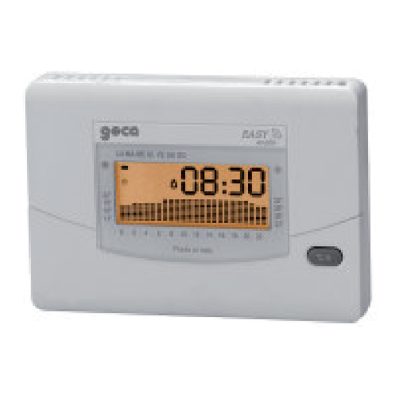
Easy Radio
CHRONOTHERMOSTAT WITH RADIO TRANSMISSION
Chronothermostat
Easy Radio
Code
Description
3.557.2147
Transmitter
3.557.2148
1-channel receiver
3.557.2151
1-channel receiver
3.557.2152
1-channel receiver
3.557.2153
1-channel receiver
WARNINGS
The unit must be installed and decommissioned by
specialist technical personnel.
The device must be installed in compliance with the domestic
laws in force.
Check that the terminals are not live before proceeding with
installation.
The use of a radio transmission device (GSM) can cause
interference with devices that do not have radiofrequency
shielding.
868,35 MHZ
Receiver
Power supply
Two 1.5V AA batteries
230Vac-50Hz
THE CHRONOTHERMOSTAT
Easy Radio is a daily and weekly electronic chronothermostat
that allows you to program the temperature in your home for
every hour and every day of the week.
Easy Radio has a backlit screen for viewing the programmed
temperatures, and simple and functional controls for user-
friendly programming.
Easy Radio saves on energy by activating the heating or air-
conditioning system only when necessary.
Easy Radio is an electronic chronothermostat with a RADIO
TRANSMITTER, meaning it does not require an electrical
connection to the boiler.
Easy Radio is powered by two ordinary 1.5V AA alkaline
batteries that guarantee use for at least 2 years.
To insert the batteries, slide off the BATTERY COVER and
put the batteries in the right way. Easy Radio has two battery
power thresholds. When the first threshold is reached, the BAT
symbol (Fig. 9) appears on the screen while the unit continues
to work normally. When the second threshold is reached, Easy
Radio disables all its heat regulation functions, and the time,
date and low battery symbol (BAT) blink on the screen.
The unit can retain the data for 30 seconds without power while
you replace the batteries.
To program the Easy Radio chronothermostat, please read the
section "OPERATION AND PROGRAMMING".
FUNCTIONS OF THE RECEIVER/RADIO BRIDGE
The JP1 jumper setting allows the RECEIVER to work in
several modes.
1 - Receiver mode (A-B) (E-F)
2 - Repeater mode (A-B) (D-E)
1 - RECEIVER MODE
Position the JP1 jumpers as shown
in Fig. 1.
In this way, the unit works as a
receiver, activating or deactivating
the load to be controlled.
2 - REPEATER (BRIDGE)
Position the JP1 jumpers as shown in Fig. 2.
This is used when:
-
The
distance
between
TRANSMITTER and the RECEIVER
is more than 100 metres, potentially
causing loss of the radio signal;
- Transmission of the radio signal is
weak due to interference.
A REPEATER is installed to prevent loss of the radio signal
between the TRANSMITTER and the RECEIVER.
A
B
JP1
D
E
Jumper
Fig. 1
A
B
the
JP1
D
E
Jumper
Fig. 2
C
F
C
F
Advertisement
Table of Contents

Related Manuals for Geca Easy Radio


Summary of Contents for Geca Easy Radio
- Page 1 2 years. To insert the batteries, slide off the BATTERY COVER and put the batteries in the right way. Easy Radio has two battery power thresholds. When the first threshold is reached, the BAT symbol (Fig.
- Page 2 (Fig. 9). Easy Radio is powered by two ordinary 1.5V AA type alkaline batteries that guarantee use for at least 2 years. To insert the batteries, slide off the BATTERY COVER and put the batteries in the right way.
- Page 3 GENERAL DESCRIPTION Press, for about 1 second, the button on the front of the In order for the Easy Radio to work properly, it has to “teach” its BRIDGE. code to the RECEIVER. The RECEIVER, connected to the device (The TRANSMITTER and the BRIDGE are coupled).
- Page 4 RADIO COVER INITIALISATION Ex.1 Power the Easy Radio and run a test cycle, turning on all the segments of the display and activating the load for a few seconds. F 1 F 2 If there is a risk that initialisation could compromise correct...
-
Page 5: Copy Button
Press the +h button to move to the DAY, which will start blinking. Use the +°C and -°C buttons to set the DAY. BARRIERS The Easy Radio is now ready for normal operation, and the flame symbol will appear on the display (Fig. 14) whenever a load (heating or air-conditioning) is activated. -
Page 6: Technical Characteristics
If the RECEIVER receives a weak signal, you are advised to ....................make a small hole in the plastic cover and extend the antenna....................TECHNICAL CHARACTERISTICS Easy radio chronothermostat ....................- Power supply: Two 1.5V AA type alkaline .................... - Page 7 A segment indicating the current day or, during programming, the CHRONOTHERMOSTAT/TRANSMITTER programmed day. B numerical display indicating the current time or ambient temperature, viewed in alternation by pressing button E. Indicates the temperature during programming. C blinking segment; indicates the external temperature or, during programming, the programmed temperature.
- Page 8 GECA Srl via E. Fermi n°98 25064 Gussago (BS) Italy Tel. +39 030 3730218 - Fax +39 030 3730228 - http://www.gecasrl.it - E-mail:info@gecasrl.it www.cavagnaindustrie.com - info@gecasrl.it GECA s.r.l. reserves the right to make aesthetic or functional changes without notice and at any time.
Need help?
Do you have a question about the Easy Radio and is the answer not in the manual?
Questions and answers