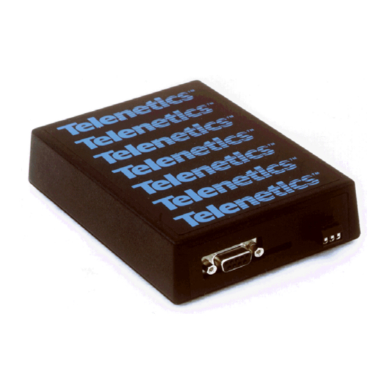
Summary of Contents for Telenetics MIU9.6FPD
- Page 1 Installation, Operation & Diagnostics for the MIU9.6FPD Industrial Grade, Digital Fast Poll Standalone Modem Document No. 49-0002-013 Rev. A...
- Page 2 Telenetics Corporation 26772 Vista Terrace Drive Lake Forest, California 92630 (949)455-4000 Fax (949)455-4010 Document No. 49-0002-013 Rev. A...
-
Page 3: Table Of Contents
8. SERIAL DATA PORT PIN-OUT ... 11 9. DIP SWITCH FUNCTIONS... 12 10. MODEM CONFIGURATION ... 14 11. LED INDICATOR... 15 12. OUTLINE DRAWING & MOUNTING... 16 13. DIAGNOSTICS ... 17 MIU9.6FPD Installation, Operation & Diagnostics April 25, 1998 Page 1... -
Page 4: Standards
1. STANDARDS Meets FCC Rules Part J, Subpart 15, Class A for radiated emissions. MIU9.6FPD Installation, Operation & Diagnostics April 25, 1998 Page 2... -
Page 5: Product Overview
Available as single channel device (MIU9.6FPD), 2-channel device (MIU9.6FPD/D) or repeater (MIU9.6FPD/R) The MIU9.6FPD can be powered from a wide range of AC and DC power supplies, it is internally surge protected on both the power and analog lines, and it will operate in temperatures from -40 to +85 deg C. -
Page 6: General Product Specifications
MIU9.6FPD/R Surge Protection: Power Supply: Analog Line: Digital Line: Operating Temperature: Operating Humidity: Storage Temperature: MIU9.6FPD Installation, Operation & Diagnostics 5.3 x 4.0 x 1.375 inches 1 lb 40 to 270VDC 40 to 270VAC, 50/60Hz 9 to 36VDC 24VDC 125VDC... -
Page 7: Modem Specifications
Asynchronous and RTS/CTS flow control Analog Interface Tx Output Level: Rx Sensitivity: Line Termination: Line Impedance: 2 or 4 Wire Configuration: MIU9.6FPD Installation, Operation & Diagnostics Pulse Position Modulation (PPM) Asynchronous Only 0 – 1200bps None None Using 16ms Polling Test... - Page 8 Anti-Streaming: RTS/CTS delay: Constant Carrier Soft Carrier Turn Off Carrier Turn ON/OFF * Dip Switch Selectable ~ See Section 9 MIU9.6FPD Installation, Operation & Diagnostics Compromise Equalization None See Section 13 See Section 13 See Section 13 See Section 13...
-
Page 9: Analog Line Specifications
5. METALLIC CONDUCTOR SPECIFICATIONS The MIU9.6FPD contains digital circuitry for connection 2 or 4-wire metallic conductors (eg; pilot wires). The MIU9.6FPD will also interface to Power Line Carrier or Microwave radio voice channel networks. The MIU9.6FPD has an RJ-11terminated connector. The following lists the MIU9.6FPD conductor interfaces... -
Page 10: Power Connections
POWER CONNECTIONS MIU9.6FPD Installation, Operation & Diagnostics April 25, 1998 Page 8... -
Page 11: Serial Data Port Pin-Out
SERIAL DATA PORT PIN-OUTS MIU9.6FPD Installation, Operation & Diagnostics April 25, 1998 Page 9... -
Page 12: Dip Switch Functions
Switch 2 Switch 3 Data Rate = 19200 bps Switch 4 Data Rate = 9600 bps Switch 5 Data Rate = 4800 bps Switch 6 Data Rate = 2400 bps MIU9.6FPD Installation, Operation & Diagnostics April 25, 1998 Page 10... -
Page 13: Led Indicator
LED INDICATOR MIU9.6FPD Installation, Operation & Diagnostics April 25, 1998 Page 11... -
Page 14: Outline Drawing & Mounting
10. OUTLINE DRAWING & MOUNTING MIU9.6FPD Installation, Operation & Diagnostics April 25, 1998 Page 12... -
Page 15: Diagnostics
Set Dip Switch 1 OFF (TxA = -10dBm) CD will be OFF. Change Dip Switch 1 to ON (TxA = 0dBm) CD should now be ON. MIU9.6FPD Installation, Operation & Diagnostics 4-Wire Soft Carrier Turn Off Enabled Transmit (TxA) Signal Level = 0dBm Receive (RxA) Signal Level = –33dBm... - Page 16 Switch 9 = ON (Soft Carrier = ON) Transmit a test message from a remote modem and confirm that the same message is received back at RxD on the remote modem with no data errors. MIU9.6FPD Installation, Operation & Diagnostics April 25, 1998 Page 14...
- Page 17 Connect TxD to RxD at the remote modem. Transmit a test message from the local modem and confirm that the same message is received back at RxD on the local modem with no data errors. MIU9.6FPD Installation, Operation & Diagnostics April 25, 1998 Page 15...
- Page 18 If there are conditions that can cause cross-talk (TxA leaking into RxA path) set Switch 1 (TxA) to OFF (-10dBm). Note that noise level should be –50dBm or lower for most FSK operation (signal-to-noise ratio of 15dB or higher) MIU9.6FPD Installation, Operation & Diagnostics April 25, 1998 Page 16...
- Page 19 MIU9.6FPD Installation, Operation & Diagnostics April 25, 1998 Page 17...
- Page 20 MIU9.6FPD Installation, Operation & Diagnostics April 25, 1998 Page 18...
- Page 21 MIU9.6FPD Installation, Operation & Diagnostics April 25, 1998 Page 19...
- Page 22 NOTES: MIU9.6FPD Installation, Operation & Diagnostics April 25, 1998 Page 20...


Need help?
Do you have a question about the MIU9.6FPD and is the answer not in the manual?
Questions and answers